
Specifications


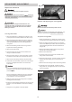


Adjust the sliding panel level:
Install the cross cut fence
1 Place a level rule (cross cut fence) on to major table
Drop the cross cut fence into the forward or rear guide
and sliding .
pin hole.
Loosen 4-M8x25 hex screws(A) , adjust the M8x40
Tighten the knurled nut.
hex screw(B) to adjust the sliding panel level(fig 13).
Turn the “Z” lock plate to quick aligning the fence to
Then re-tighten 4-M8x25 hex screws (A).
table.
To fine adjust, using 3 mm “L” wrench to adjust 4-
4 the and clamped the fence in
M8x12 set screws(C).
position.
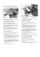
Install the push handle and lock pin
Slide the flip stop(D) into the fence.
1 Sliding the M12x1.75 T-nut into the sliding panel and
6.Place a T-nut into the top slot of fence, thread the
thread in push handle(D) with a 17 mm open end
stud of hold-down on fence.
wrench.
7.If need, put the hold down arm onto the stud (E).
Insert the star-type lock pin (E) into sliding panel, and
lock the M10 hex nut on the opposite side.
Install the cross cut table
Slide two l into the
side slot of sliding . Attached the crosscut table
to sliding .
Use 2 wing nuts mounted the cross cut table to sliding
panel.
Install the hold down/Mitre Gauge
3 Use 2 M6x30 Hex head scews mounted the cross cut
table to support(B).
Slide the hold down/Mitre Gauge onto the sliding
table and push it as far as possible. And lock the hold
4 Adjust 4-M12 thin hex nut (C) to adjust the cross cut
down/mitre gauge on table with the star-type lock
table on the line with sliding panel.
handle (A) locked.
Then tighten 4-M12 thin nut (C).
ligned the Mitre Gauge fence on it.
.
1.
panel
2.
2.
3.
3.
4.
.Turn star type screw
5.
.
2.
1. M8x70 carriage bolts with T- blocks
panel
panel
2.
.
1.
.
5.
2. A
D
E
C
B
11
Fig 15
Fig 16
Fig 18
D
Fig 1
E
D