Code 508338 T-2000CK-200H 2hp Cyclone Extractor AT&M: 26/03/2015 REF: 508500
Index of Contents Index of Contents Declaration of Conformity What’s Included General Safety Instructions for 230V Machines Specification Assembly Machine Footprint Illustration and Parts Description Operating Instructions Ducting System Maintenance Weekly LEV System Maintenance Log LEV Testing Extraction Accessories Exploded Diagram/Parts List Wiring Diagram Notes 02 03 04-05-06 07-08 08 08-09-10-11-12-13-14-15-16 17 18-19-20-21 22-23 23 24 25-26 27 27 28-29 30 31 Declaration of Conformity Copied from CE
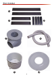
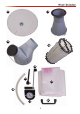
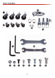
What’s Included Quantity Item Part 1 No T-2000CK-200H Cyclone Extractor 1 No 4 No 4 No 2 No 2 No 4 No 1 No 1 No 1 No 1 No 1 No 1 No 1 No 1 No 1 No 1 No 1 No 1 No 2 No 1 No Motor Assembly Upper Leg Square Tubes Lower Leg Square Tubes Long Cross Support Brackets Short Cross Support Brackets Leg Bracket Connectors Extractor Drum Flexible Hose Bin Bin Cover Filter Lid (Air Filter Cartridge) Extraction Funnel Inlet Manifold Air Filter Cartridge Shaker Paddle Operating Handle Operating Handle Extension Bar
What’s Included 4 5 6 7 8 9 10 4
What’s Included 11 12 13 14 15 16 19 18 20 17 5
What’s Included 23 21 22 24 27 a 25 26 b c d e 6 f g h
General Safety Instructions for 230V Machines Good Working Practices/Safety The following suggestions will enable you to observe good working practices, keep yourself and fellow workers safe and maintain your tools and equipment in good working order. WARNING!! KEEP TOOLS AND EQUIPMENT OUT OF THE REACH OF YOUNG CHILDREN Mains Powered Tools and Machines Primary Precautions These machines are supplied with a moulded 16 Amp plug and 3 core power cable.
General Safety Instructions for 230V Machines If the particle filter starts to clog, this reduces the air flow and hence the machine becomes less efficient. If possible, try to connect everything together electrically, to eliminate static shocks. The particle filter can be cleaned, by using an ‘M’ class vacuum cleaner, clean the inside of the filter. (Use the integral metal coil in flexible plastic hosing to connect units together).
Assembly Having unpacked the boxes, put all components where they are readily to hand. Locate the motor assembly (1), the upper and lower leg square tubes (2-3), cross support brackets (4-5), leg connectors (6) and 5/16” button head bolts (e). 2. Locate the four leg bracket connectors (6) and lower leg square tubes (3).
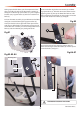
Assembly 4. Locate the two long and short cross support brackets (4-5). Line up the pre-drilled holes in one of the cross support brackets with the pre-drilled holes to the front face of the lower leg support tubes (3). Secure using four button head bolts (e), see fig 08. Repeat for the remaining cross support brackets, see fig 09-10. 5. Locate the four castor wheels (21).
Assembly 7. Locate the extraction funnel (12). Loosen the clamping rig bolt/nut to the base of the funnel, lower the wide end of the funnel on top of the drum (7) and line up the rims. Position the clamping ring over the rims and tighten the bolt/nut to lock both units (7-12) together, see 16-17-18. Fig 19 26 Fig 16-17-18 a g Fig 20-21-22 12 10 7 g Clamping ring Rim 26 8. Locate the bin cover (10), 1/4 “ Hex bolts (g), 1/4" nuts (a) and the supplied 10-12mm spanner (26).
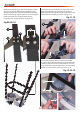
Assembly You will require the bin (9), bin castor wheels (22), bin lever clamps with Phillips screws and nuts (25), bin handle (20), 1/4” domed nuts (b), 1/4” button head Phillips screws (f ), dust bag (19), flexible hose (8) and large and small clips (24). Fig 27-28 9. Turn the bin (9) on its side and screw on the four castor wheels (22) into the threaded holes to the base of the bin, tighten the nuts using the supplied 6-7mm spanner (26), see fig 23-24-25. Fig 23-24-25 22 9 Inner bin section 26 10.
Assembly Fig 33-34 8 12. Locate the bin handle (20), button Phillips screws (f ) and domed head nuts (b). Line up the threaded holes in the handle (20) with the two pre-drilled holes in the bin (9) and secure in place with the 1/4" Phillips screw (f ) and nuts (b), see fig 31-32. 24 Fig 31-32 b 14. Locate the large dust bag (19), open the bag and place it inside the bin (9), see fig 35. (Make sure the bag is tucked over the edge of the bin) Fig 35 f 19 20 13.
Assembly 16. Locate the air filter cartridge (14) and six 5/16" Hex bolts (h), with assistance position the filter cartridge under the motor assembly housing (1) and line up the threaded holes in the filter with the holes in the motor housing, see fig 38. 18. Put to hand the operating handle extension bar (16), loosen the two cap head screws on the drive socket and slot the Hex drive over the shaker paddle drive shaft, see fig 42. Tighten the cap head screws to secure the extension bar (16), see fig 43.
Assembly Fig 49-50 Fig 46 d 19 20. Find the shaker paddle operating handle (15) and M6 x12mm bolt (c). Insert the handle’s drive socket onto the shaker paddle’s drive shaft and screw on the M6 bolt (c) into the threaded hole to the side of the machined aperture. Tighten using the supplied spanner (26), see fig 47-48. 23 Fig 47-48 underside of the motor assembly housing (1) and secure using the Hex bolts (h), see fig 51-52. 15 Fig 51-52 Threaded hole Mounting bracket NVR switch 26 c h 21.
Assembly 23. Locate the manometer (17), manometer hose (18) and the two small clips (24). From the opposite side of the extractor insert the hose (18) through the hole to the centre of the NVR’s mounting bracket, see fig 53. 26. To the underside of the motor assembly housing remove the two Hex bolts and place to one side in readiness for the next step, see fig 56. Fig 56 24.
Machine Footprint 1,800mm mm 00 1,0 mm 1,250 17
Illustration and Parts Description 15 A 11 1 7 2 17 13 B 14 12 4 3 10 23 19 22 9 20 18 25 21
Illustration and Parts Description Manometer Vacuum Gauge indicator to monitor the air flow in the ducting system NVR Switch assembly Green (ON) Emergency Stop (Red) Part Description 1 Motor Assembly 2 Upper Leg Square Tubes 3 Lower Leg Square Tubes 4 Long Cross Support Bar 5 Short Cross Support Bar 7 Extractor Drum 8 Flexible Hose 9 Bin 10 Bin Cover 11 Filter Lid 12 Extraction Funnel 13 Inlet Manifold 14 Air Filter Cartridge 15 Shaker Paddle Handle 17 Manometer 18 Manomet
Illustration and Parts Description 18 24 8 24 20
Illustration and Parts Description Pull up the bin lever clamp handles to release bin Pull the bin out to empty the contents Rotate the shaker paddle operating handle to remove any build up of dust inside the filter 21
Operating Instructions 2. Start up the extractor by pressing the ‘green’ button on the NVR switch assembly and check the reading on the manometer. HSE Health and Safety Executive To operate the cyclone extractor correctly, it is recommended to visit the HSE (Health and Safety Executive) website at www.hse.gov.uk and read the information on the safe practices. 3. Using a marker or sticky label mark the reading on the manometer, see fig 62.
Operating Instruction and Ducting System Fig 63 Fig 64-65-66 General Info Many manufacturers will state the volume of air required for each machine in their manual. If not, note the size of the extraction port and use the chart below. outlet size volume of air required 50 200 m³/hr 100 700 m³/hr 125 1100 m³/hr 150 1600 m³/hr 200 2800 m³/hr Example: for a single machine with a 100mm port, an extractor of a minimum of 700m³/hr will be sufficient.
Maintenance Fig 67 WARNING! BEFORE CARRYING OUT ANY MAINTENANCE DISCONNECT THE CYCLONE EXTRACTOR FROM THE MAINS SUPPLY WARNING! KEEP CHILDREN AWAY FROM WORK AREA WARNING! ALWAYS WEAR A DUST MASK WARNING! ALWAYS WEAR EYE PROTECTION Fig 68 After a period of time dust, sawdust and shavings can build-up causing blockages and reduced suction performance. Follow the maintenance instructions below to keep your extractor working at peak performance.
12 24 25 Comments Empty waste collectors if necessary Check waste collector(s) for damage and condition Check filter shakers (if fitted) and clean filters Check filter(s) for damage and condition Check operation of all blast gate controls Check inlets, clear any obstructions if found Check all ducting for physical damage Checked by Date Week Weekly LEV System Maintenance Log 1 2 3 4 5 6 7 8 9 10 11 REMOVE AND CLEAN FILTERS 13 14 15 16 17 18 19 20 21 22 23 REMOVE AND CLEAN F
52 53 54 55 56 57 58 59 60 26 36 49 50 51 Nearly 14 months it is now a legal requirement to have your system tested and certified Comments Empty waste collectors if necessary Check waste collector(s) for damage and condition Check filter shakers (if fitted) and clean filters Check filter(s) for damage and condition Check operation of all blast gate controls Check inlets, clear any obstructions if found Check all ducting for physical damage Checked by Date Week Weekly LEV System Mainten
LEV Testing Why should I bother with LEV? Ref Code: HSG258 The law says you must control the risks from these substances (the Control of Substances Hazardous to Health (COSHH) Regulations). Installing LEV may help you to do this. The book above provides guidance on the supply of local exhaust ventilation (LEV) equipment. It describes the principles and good practice of deciding on, designing, commissioning and testing cost-effective LEV.
Exploded Diagram/Parts List 28
Exploded Diagram/Parts List NO 1 2 3 4 5 6 7 8 9 10 11 12 13 14 15 16 17 18 19 20 21 22 23 24 25 26 27 28 29 30 31 32 33 34 35 36 37 38 Description Motor Main Housing Aluminum Impeller Round Collector Reducing Collector Upper Leg Leg Connecting Bracket Lower Leg PE Bag PE Bag Ball Caster 2” Caster 3” Caster 3” BARREL CLAMP 347 N Type Handle Switch Plate Magnetic Switch 2hp Hose Clamp 1-3/4” Inlet Motor Cord Power Cord W/ Plug Flange Bolt 5/16”x1/2” Tap Screw Flange Bolt5/16”x 3/4 Cap Nut 5/16’’ Flange Bolt
Wiring Diagram Single Phase Teminal Jumper Power Sourse 30
Notes 31
The Axminster guarantee is available on Hobby, Trade, Industrial, Engineer, Air Tools & CNC Technology Series machines It’s probably the most comprehensive FREE guarantee ever- buy with confidence from Axminster! So sure are we of the quality, we cover all parts and labour free of charge for three years! • Look for the icon and put your trust in Axminster • No registration necessary - just keep your proof of purchase • Optional Service Plan for Industrial Series machinery AXMINSTER Hobby SERIES Great val