Code 508310 Code 508312 AXMINSTER Hobby SERIES Product Kits TS-200-2 & TS-250M-2 Basic Table Saws Whole assembly instructions including leg stand extension table and sliding table kits Leg Stand 501248 - TS-200-2 508213 - TS-250M-2 Sliding Table Kit 501254 - TS-200-2 508214 - TS-250M-2 TS-200-2 Code: 508310 R/H Extension Table 508311 - TS-200-2 508313 - TS250M-2 Table Saw Complete Kit 717666 - TS-200-2 717667 - TS- 250M-2 TS-250-2 Code: 508312 AT&M: 24/02/2015 REF: 508472
Index of Contents Index of Contents Declaration of Conformity What’s Included Optional Accessories General Instructions for 230V Machines Specific Instructions/Precaution for the Saw Table Specification Assembly Illustration and Parts Description Setup and Adjustments Operating Instructions Changing the Saw Blade Parts Breakdow/List Wiring Diagram CE Certificates Notes 02 02 03-04 05-06 07-08 08 09 09-10-11-12-13-14-15-16-17-18-19-20-21 22-23-24-25 26-27-28 29-30 30-31 32-33-34-35-36-37-38-39 39 40-41 42-4
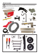
What’s Included Quantity Item Part Model Number MJ10-SB200 / MJ10-SB250 (TS-200-2 Kit Code: 508310) (TS-250M-2 Kit Code: 508312) 1 No 1 No 1 No 1 No 2 No 1No 2 No 1 No 1 No 1 No 1 No 2 No Basic Table Saw Assembly Basic Table Saw and Kerf Plate with Phillips Screws A Riving Knife A1 Table Insert Height Shims A2 Micro Adjuster ( TS-250M-2 ONLY) A3 Hose Support Bracket and fixing Cap head Screws/nuts A4 Crown Guard with Flexible Hose B Dust Extraction Moulding with four Phillips Screws C Mitre F
What’s Included Having unpacked your saw and its accessories please dispose of any unwanted packaging properly. The packaging is biodegradable.
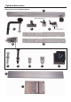
Optional Accessories Leg Stand (Kit Codes: 501248 & 508213) K H I L J L1 L2 R/H Extension Table (Kit code: 508311 & 508313) M N O Q1 Q3 Q2 P Q 5
Optional Accessories Sliding Table (Kit code: 501254 & 508214) R Work clamp block S T U W W1 Connecting block V W2 W3 W4 X Y 6 R1
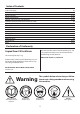
General Instructions for 230V Machines not use any solvents or cleaners, as these may cause damage to any plastic parts or to the electrical components. Keep the work area as uncluttered as is practical, this includes personnel as well as material. Good Working Practices/Safety The following suggestions will enable you to observe good working practices, keep yourself and fellow workers safe and maintain your tools and equipment in good working order.
General Instructions for 230V Machines Above all, OBSERVE…. make sure you know what is happening around you and USE YOUR COMMON SENSE. Check that blades are the correct type and size, are undamaged and are kept clean and sharp, this will maintain their operating performance and lessen the loading on the machine. Specific Instructions/Precaution for the Saw Table Make sure the saw blade is the correct type for the job in hand.
Specification Code 508310 Model TS-200-2 Basic Rating Hobby Power 1.1kW 230V, 1ph Blade Dia/Bore 205mm/30mm Blade Tilt 0° to 45° Max Depth of Cut @ 45˚ 40mm Max Depth of Cut @ 90˚ 60mm Max Width of Cut with Fence 190mm standard, 750mm with R/H Table Kit Table Size 675 x 400mm Table Height 320mm Dust Extraction Outlet 100mm Min Extraction Airflow Required 500m³/hr Overall L x W x H 800 x 400 x470mm Weight 55kg Code 508312 Model TS-250M-2 Basic Rating Hobby Power 1.
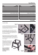
Assembly Mounting the Saw Bench to the Stand 1. With assistance, place the Saw Bench (A) onto the stand. Align the four mounting holes at the base of the saw bench with the four mounting holes at each corner of the stand. Using four M8 x 16mm hex bolts, large washers & nuts (L2) secure the saw bench to the stand, see figs 05-06. Now tighten all the nuts on the stand assembly. Fig B Tilt mechanism shaft Fig 05 A 2. Slide the mitre fence (D) into one of the tables ‘T’ slots, see fig 08. 3.
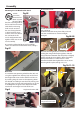
Assembly 5. Locate the crown guard and flexible hose (B). Remove the clamping pin bolt, washer and lift and shift handle from the crown guard assembly, slot the guard down over the riving knife (A1) until the holes are in line then replace the pin bolt, washer and clamping handle, see figs 13-14. Fig 13-14 Pin bolt B 7. Remove the three nuts and washer from the fence rail (F) and place safely aside.
Assembly Rip fence extension 9. Move the fence (E) until it’s in line with the tables ‘T’ slot, see fig 20. If the fence is out of alignment loosen the four cap head screws on top of the rip fence assembly and adjust the fence until its in alignment with the ‘T’ slot, re-tighten the cap head screws, see fig 21-22. Fig 20 ‘T’ Slot E Fig 21-22 Cap head screws Hex key 11. Slide the rip fence assembly (E) up against the blade and check the index marker on the magnifying glass reads ‘zero’ on the scale.
Assembly 13. Lift up the fence clamping handle, push in and turn the control knob on the micro adjuster (A3) and check it tracks smoothly down the fence rail (F), see fig 31. Fig 31 Micro Adjuster (TS-250M-2 ONLY) 12. Locate the micro adjuster (A3), remove the end cap from the rip fence assembly (E), see fig 28. Insert the mounting blocks on the micro adjuster (A3) into the ‘T’ slot to the side of the rip fence assembly.
Assembly 15. Attach the hose support bracket (A4) to the far corner of the saw table using two cap head screws and nuts, see fig 34-35. Fig 37 Fig 34-35 Cap head screws Hex key Fig 38 A4 16. Locate the flexible hose (B) and hose clips (G2). Place a clip over one end of the hose and insert the hose over the 50mm outlet on the extraction moulding (C) and tighten the hose clip, see fig 36. Fig 36 R/H Extension Table Kit 1.
Assembly Fig 39 Fig 42-43 Q1 Q2 M 4. Remove the washers/nuts from the remaining three bolts and place aside, position the bolts along the rail, put to hand four cap head screws (Q1) and washers (Q2), see fig 40. 5. Slot the three bolts in the fence rail (M) through the three holes in the extension table (P), see fig 41 lift up the table (P) and align the four holes to the side with holes in the saw table and secure using cap head screws/washers, see fig 42-43. 6.
Assembly 8. Locate the rear rip fence guide rail (O), line up the holes and the machined cutouts with the ‘T’ slots to the rear of the saw table (A), see fig 46. Insert three cap head screws with washers through the guide rail (O) into the threaded holes in the saw table, lightly tighten with a Hex key. Place the further three cap head screws with washers through the guide rail and extension table (P), secure with the remaining washer and nuts (Q3), see figs 47-48.
Assembly A4 12. Replace the rip fence assembly (E) onto the front fence rail (F). Remove the short rip fence from the main assembly by removing the four cap head screws, place safely aside, see fig 54-55. Fig 54-55 14. Move the fence (E) until it’s in line with the table’s ‘T’ slot, if the fence is out of alignment loosen the four cap head screws on top of the rip fence assembly, see fig 57 and adjust the fence until its in alignment, re-tighten the cap head screws. 15.
Assembly Fig 58 Fig 61 V a Fig 59-60 Threaded nuts w3 W2 Fig 62 V Pre-drilled holes w1 V Fig 63 X 2. Place an M6x16mm Hex bolt (W3) in each of the four clearance holes on both support arms (V) and loosely screw on an M6 nut and washer, see fig 61. ‘T’ Slot w3 3. Locate the four M6x30mm Hex Bolts (W1) and lightly screw each bolt into the threaded holes to the underside of the carriage arm (X), see fig 62.
Assembly Fig 64-65 Fig 67 Y W4 Angle Fence 1). Put to hand the work clamp block (U), and slide it into the T-slot on the angle fence (R). Locate the connecting block (U) and slide it onto the angle fence as before, see figs 68-69. Slide the T-bolt on the base of the connecting block (U) into the T-slot on the sliding carriage table (Y), see figs 70-71. Locate the plastic block and Phillips screws (R1), secure it to the end of the angle fence (R), see fig 72. Carriage arm rail Fig 68-69 6.
Assembly Fig 70-71 Fig 73-74 ‘T’ Slot Y S U Lift and shift handle Connecting block Lift and shift handle Angle fence stop ‘T’ Bolt Fig 72 Fig 75 R1 The picture above shows the angle fence (R) removed from the carriage table for clarity. 2. Locate the work clamp (S), slot the work clamp into the 20mm hole in the work clamp block (U), secure in position with the lift and shift handle, see fig 73. To set the angle fence at 90˚, push the angle fence (R) up against the stop, see fig 74. 3.
Assembly Fig 76-77 Fig 80 T Grub locking screw R 5. Locate the flip over stop (T) and slide it into the T-slot on top of the angle fence (R), see fig 80. Tighten the butterfly knob. Eccentric bush carriage table (Y), see figs 78-79. Tighten the three lift & shift handles to lock the angle fence in position. Note: The fence can also be used at the rear of the sliding carriage table if you prefer to push the timber against the fence.
Illustration and Parts Description Rip fence extension Work clamp block Flexible hose Crown guard Sliding table assembly Hose support bracket Connecting block R/H extension table Basic table saw Tilt operating wheel Stand TS-200-2 Complete Kit Crown guard clamp Flip over stop Work clamp Sliding carriage table Rip Fence assembly Rear guide rail Carriage arm Mitre fence Front fence rail Rip fence extension clamping handles TS-250M-2 Complete Kit Rise & fall operating wheel 22 Extension table s
Illustration and Parts Description TS-200-2 Basic Saw TS-250M-2 Basic Saw 23
Illustration and Parts Description Clamping knob Shroud OFF ON Scale Pointer Mitre fence assembly NVR ON/OFF switch with emergency stop shroud Adjusting screw Pointer Scale Tilt operating wheel Tilt scale pointer and adjusting screw Tilt mechanisum clamp Scale Rise and fall operating wheel and the clamping handle for the tilt mechanisum Carriage table scale for measuring set angles 24
Illustration and Parts Description Clamp A B Work clamp block (A) and connecting block (B) Flip over stop assembly Scale A C Fence rail scale B Crown guard (A), Blade (B) and Riving knife (C) Saw blade assembly set at 45˚ B A C Rip fence clamp (A), Rip fence extension (B) and micro adjuster (TS-250M-2 Only) (C) 25 100mm Dust extraction outlet
Setup and Adjustment The Riving Knife Adjusting the Rip Fence to the Blade 1. Raise the saw blade to its highest point and remove the saw blade crown guard, see fig 13-14 on page 11. The fence assembly must be parallel to the saw blade for producing accurate cuts. 2. Remove the four Hex screws and place carefully aside, remove the table insert, see fig 81.
Setup and Adjustment 4. The rip fence extension can be repositioned from the vertical to a horizontal position for guiding thin timber pieces through. Loosen the two clamping handles holding the fence extension, remove, lay the fence extension down in the horizonal position and remount the fence extension as before,see fig 87. Move the extension down until the end face is centred with the blade and tighten the two clamping handles to lock the assembly, see fig 88.
Setup and Adjustment Setting the Blade Alignment If the blade is not cutting 100% true, the blade is out of alignment. Follow the instructions below on how to set the blade to the table. 1. Remove the blade crown guard and table insert, see fig 93. 2. Loosen the four Hex screws (A), see figs 93-94. 4. Place the rule to the opposite end of the blade and take a further reading, see fig 96. 6.
Operating Instructions Fig 99 NOTE: BEFORE USING YOUR SAW, GO ROUND AND MAKE SURE EVERYTHING IS SECURE, FASTENED DOWN, THAT ALL TOOLS ARE CLEARED AWAY FROM THE WORK AREA! CHECK: THE BLADE FOR SHARPNESS,MISSING TEETH, RESIN BUILD UP ECT., CLEAN IF NECESSARY. CHECK THE BLADE IS SECURELY CLAMPED IN PLACE (I.E. NOT LOOSE)! Fig 100 CONNECT THE SAW TO THE MAINS SUPPLY! Give the machine a ‘quick’ burst check ( i.e. quick ON-OFF) to ensure everything is O.K.
Operating Instructions Fig 102 Fig 103 THE BLADE IS SET AT AN ANGLE LESS THAN 90˚ DEGREES FOR BEVEL CUTS HOLD THE WORK FIRMLY LOCK THE MITRE FENCE AND HOLD THE WORK FIRMLY BLADE GUARD Changing the Saw Blade 1. Raise the saw blade to its highest point, remove the saw blade guard, remove the four Hex screws that secure the table insert, place carefully aside and remove the table insert, see fig 104.
Changing the Saw Blade 6. Check the old blade for sharpness, missing teeth, resin build up, etc., clean if necessary and send for refurbishment/resharpening if required. If the blade is not to be re-sharpened, clean and pack away in its storage case. Fig 106 Fig 107 Sawplate washer Blade Maintenance 1. Keep the saw as clean and free from saw dust build up as is practical. Periodically, remove the saw gullet and vacuum out and clean out the saw box and the extraction housing.
Parts Breakdown/List TS-200-2 and TS-250M-2 (Motor Housing Exploded Diagram) 32
Parts Breakdown/List Qty 36 Ball bearing 1 1 Set screw 1 37 C-Spring 1 2 Shaft 1 38 Shaft 1 3 Hand wheel 1 41 Supporting plate 1 4 Pin 1 42 Washer 2 5 Sharp 1 43 Nut 2 6 Pin 1 44 Washer 1 7 Lead screw nut 1 45 Nut 2 8 Motor 1 46 Washer 1 9 C-Spring 1 47 Lever 2 10 Motor guidance plate 1 48 Sawing base 1 11 Arbor 1 49 Pin 1 12 Washer 3 50 Screw 1 13 Set Screw 3 51 Washer 1 14 Set Screw 2 52 Connecting plate 1 15 Washer
Parts Breakdown/List 74 Nut 1 107 Lens 1 75 Table 1 108 Taping screw ST4.
Parts Breakdown/List TS-250M-2 (Table & Fence Exploded Diagram) 35
Parts Breakdown/List TS-200-2 (Table & Fence Exploded Diagram) 36
Parts Breakdown/List Part No Description Qty 85 Flat washer 1 56 Hand wheel 1 86 Bearing Bar 1 57 Screw 2 87 Bearing 2 58 Nut 1 88 Small handgrip 1 59 Thread shaft 1 98 Connecting plate 1 60 Plate 1 99 Flat washer 5 1 61 Clamp 2 100 Fence extrusion aluminium 1 62 Dust extraction hose 1 101 Push 4 63 Base 1 102 Screw M6×65 4 64 Switch box 1 103 Fence “L”shape 1 65 Switch 1 104 Carriage screw M6×70 2 66 Clamp for cord 1 105 Screw 2 67 Se
Parts Breakdown/List Sliding Table Exploded Diagram 38
Parts Breakdown/List Qty 17 Screw M4 x 12 2 1 C-shaped ring 1 18 Wood block 1 2 Sliding axle 1 20 Angle fence 1 3 Eccentric bush 1 21 E’ ring ɸ 16 1 4 Hex thin nut M8 1 22 Press handle 1 5 Set screw M8 x 25 1 23 Square toes nut 1 6 Eccentric nut 2 24 Angle.
CE Certificate 40
CE Certificate 41
Notes 42
Notes 43
The Axminster guarantee is available on Hobby, Trade, Industrial, Engineer, Air Tool & CNC Technology Series machines It’s probably the most comprehensive FREE guarantee ever- buy with confidence from Axminster! So sure are we of the quality, we cover all parts and labour free of charge for three years! • Look for the icon and put your trust in Axminster • No registration necessary - just keep your proof of purchase • Optional Service Plan for Industrial Series machinery Great value & easy-to-use, perfect