Code 501215 UB-801F Extractor
CONTENTS: IMPORTANT SAFETY RULES -------------------------------------------------------------- 2 SAFETY LABEL --------------------------------------------------------------------------------- 5 GROUNDING INSTRUCTIONS ------------------------------------------------------------- 7 SPECIFICATIONS ------------------------------------------------------------------------------ 8 CONTENTS OF PACKAGE & TRANSPORTATION------------------------------------ 9 ASSEMBLY INSTRUCTION --------------------------------------
IMPORTANT SAFETY RULES Wood working can be dangerous if safe and proper operating procedures are not followed. As with all machinery, there are certain hazards involved with the operation of the product. Using the machine with respect and caution will considerably lessen the possibility of personal injury. However, if normal safety precautions are overlooked or ignored, personal injury to the operator may result.
Safety Contents: 1. CAUTION: This appliance is not suitable for picking up hazardous dust. 2. CAUTION: This appliance is for dry use only and is not to be used or stored outdoors in wet conditions. 3. Regularly examine the supply cord for damage. If damaged, replace the cord specified, before further use. 4. Only replace the supply cord with the type specified In the Instructions. 5. Only use the socket outlet/or plug on the appliance for purposes specified in the instruction manual 6.
IMPORTANT SAFETY RULES FOR DUST COLLECTORS WARNING: Basic precautions should always be 11. DO NOT unplug the dust collector by pulling on followed when using your dust collector. To reduce the the power cord. ALWAYS grasp the plug, not the risk of injury, electrical shock or fire, comply with the cord. safety rules listed below: 12. 1. READ and understand the instruction manual before operating the dust collector. DO NOT handle the plug or dust collector with wet hands. 13. 2.
GROUNDING INSTRUCTIONS The appliance must be grounded; if it should malfunction or breakdown, grounding provides a path of least resistance for electric current to reduce the risk of electric shock. This appliance is equipped with a cord that has a equipment-ground conductor and grounding plug. The plug must be inserted into an appropriate outlet that is properly installed and grounded in accordance with all local codes and ordinances.
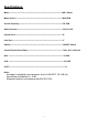
Specifications: Motor-----------------------------------------------------------------------------------------1HP/1 Phase Motor Speed------------------------------------------------------------------------------- 2850 RPM Suction Capacity------------------------------------------------------------------------- 700 CFM Static Pressure---------------------------------------------------------------------------- 5.
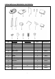
UNPACKING & CHECKING CONTENTS: NO. A B C D E F G H I J K L M N O P Description Housing Base Hanger Wheel Upper Bag Right Stand Left Stand Bag Clamp Handle Fixing Plate Polyester Bag Blast Gate Y-Inlet Hose Clamp Hose Reducing Connector Specification 4” 4” 4” 7 Q’TY 1 1 1 4 1 1 1 2 1 1 1 1 1 2 1 Part List No. NO.3 NO.19 NO.30 NO.22 NO.1 NO.15 NO.14 NO.2 NO.8 NO.17 NO.16 NO.36 NO.32 NO.35 NO.37 1 NO.
Hardware package: NO. Description Specification Q’TY Part List No. 5/16”*1/2” 16 NO.13 5/16”*1-1/4” 4 NO.7 10*12 1 NO.31 A Flange Bolt B Flat Head Screw C Open Wrench D Phillips Head Screw 3/16”*1/4” 4 NO.40 E Phillips Head Screw 3/16”*3/8” 2 NO.
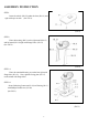
ASSEMBLY INSTRUCTION STEP1. Insert the wheels (NO.22) under the base (No.19) and tight with open wrench. (See FIG.1). (FIG.1) STEP2. Place the housing (NO.3) on the right stand (NO.15) and left stand (NO.14) tight with flange bolts. (NO.13) (See FIG.2) (FIG.2) STEP3-1. Place the stand and housing set on the base tight with flange bolt. (NO.13) Next, tight the fixing plate (No.17) on the stands with flange bolts. STEP3-2. Secure Reducing Connector(No.34) on Housing (No.3) with Phillips Head Screw (No.
STEP4-1. Place the handle (NO.8), on the top of the housing (NO.3) and tight with flat head screw. (NO.7) STEP4-2. Insert the hanger (NO.30) into the holes of the housing top. (See FIG.4) STEP4-3 Attach Y Inlet (No.32) on Reducing Connector (No.34) and then use Hose (No.37) to connector Reducing Connector (No.34) and Blast Gate (No.38) also tight Hose (No.37) with Hose Clamp (No.35) (FIG.4) STEP5. Place the upper bag (N0.1) and lower polyester bag (NO.16) on the top and bottom of the housing (NO.
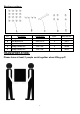
OUTSIDE DIMENSION: 11
EXPLODED DIAGRAM: 12
Part List: NO.
The Axminster guarantee is available on Hobby, Trade, Industrial, Engineer, Air Tools & Axcnc Technology Series machines It’s probably the most comprehensive FREE guarantee ever- buy with confidence from Axminster! So sure are we of the quality, we cover all parts and labour free of charge for three years! • Look for the icon and put your trust in Axminster • No registration necessary - just keep your proof of purchase • Optional Service Plan for Industrial Series machinery Great value & easy-to-use, perfe