Installation Instructions Starck 10650181 Starck 10971181 Starck 10750181 Starck 28486181
Rough Required Trim (not included) Starck Thermostatic Module 10750181 Trim for Starck Thermostatic Module 10751XX1 Starck Volume Control 10971181 Trim for Starck Volume Control 10972XX1
Rough Required Trim (not included) Starck Handshower System Rough 10650181 Starck Handshower System 10651XX1 Shower Module Rough 28486181 Shower Module 28491XX1
Rough Trim (not included) Rough for Small Shelf / Extension Pipe 40877180 Shelf 40872XX0 Rough for Large Shelf / Extension Pipe 40878180 Shelf 40873XX0 Technical Information Max. water pressure Recommended water pressure Max. hot water temp Recommended hot water temp Hot and cold connections Max. flow rate 145 psi 15 - 75 psi 176°F* 120°-140°F* ¾" NPT 15 gpm @ 44 psi *Know and follow all applicable local plumbing codes when setting the temperature on the water heater.
Installation Suggestions The next pages include some showers using the Starck Shower System. These are not the only systems possible. If you have questions regarding your installation, please call Hansgrohe Technical Service at 800 334 0455.
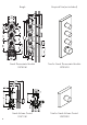
Showerheaven 30x30 10625XX1 ½" NPT 40871XX1 40874XX0 40876180 40872XX0 10973181 28486181 10971181 28491XX1 ½" NPT 10972XX1 10750181 10751XX1 28486181 10650181 28491XX1 10651XX1 ¾"NPT ¾" NPT
Showerheaven 30x30 10625XX1 40871XX1 40874XX0 40872XX0 28491XX1 10972XX1 10751XX1 28491XX1 10651XX1
Showerheaven 30 x 30 10625XX1 28491XX1 (4x) ½" NPT 28486181 (4x) 10650181 40878180 ¾" NPT 10971181 10750181 10651XX1 ¾" NPT 40873XX0 ¾" NPT 10972XX1 10751XX1
Showerheaven 30x30 10625XX1 28491XX1 (4x) 10651XX1 40873XX0 10751XX1 10972XX1
see page 26 28491XX1 (6x) 28491XX1 ½" NPT ½" NPT ½" NPT 40872XX0 ½" NPT 28491XX1 ¾" NPT 10651XX1 ¾" NPT 28486181 10751XX1 ½" NPT 40877180 10650181 ½" NPT 10750181 28491XX1 28491XX1 ¾" NPT ¾" NPT 10
28491XX1 (6x) 28491XX1 10651XX1 10751XX1 40872XX0 11
Showerheaven 30 x 30 10625XX1 ½” NPT 40872XX0 10751XX1 10651XX1 10750181 10650181 ¾" NPT 12 ¾" NPT
Showerheaven 30 x 30 10625XX1 40872XX0 10751XX1 10651XX1 13
Rainfall 28411XX1 ½" NPT ½" NPT 40872XX0 ½” NPT 10751XX1 10651XX1 10750181 10650181 ¾" NPT 14 ¾" NPT
Rainfall 28411XX1 40872XX0 10751XX1 10651XX1 15
Showerheaven 30 x 30 10625XX1 ½" NPT 10650181 10750181 10651XX1 ¾" NPT ¾" NPT 10751XX1 40873XX0 16
Showerheaven 30 x 30 10625XX1 10651XX1 40873XX0 10751XX1 17
28491XX1 (4x) ½" NPT 28491XX1 ½" NPT 28491XX1 28486181 ¾" NPT ½" NPT ¾" NPT 10750181 28486181 10751XX1 ½" NPT 28491XX1 ½" NPT 28491XX1 ¾" NPT ¾" NPT 18
28491XX1 (4x) 28491XX1 10751XX1 19
28491XX1 (4x) 28491XX1 (1x) ½" NPT 28491XX1 ½" NPT 10650181 28486181 ½" NPT 10750181 28491XX1 10651XX1 ½" NPT 10751XX1 28491XX1 ¾" NPT ¾" NPT 20
28491XX1 (5x) 28491XX1 28491XX1 10751XX1 10651XX1 28491XX1 21
28491XX1 (4x) ½" NPT 28491XX1 ½" NPT 28486181 (3x) ½" NPT 27980000 10750181 27458000 ¾" NPT ¾" NPT 10751XX1 22
28491XX1 (4x) 27980000 27458000 28491XX1 10751XX1 23
28491XX1 (4x) ½" NPT 28491XX1 ½" NPT ¾" NPT 28486181 27980000 28491XX1 10750181 27458000 ½" NPT 10751XX1 28491XX1 ¾" NPT ¾" NPT 24
28491XX1 (4x) 27980000 28491XX1 27458000 28491XX1 10751XX1 28491XX1 25
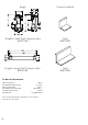
Installation Notes The 10750181 thermostat module includes two plugs. Handshower module 10650181 and volume control 10971181 each include one plug. If ½" NPT pipe is to be connected to the end of a valve, cut the plug as shown to create an adapter. If nothing is connected to the end of a valve, seal it using an uncut plug. 10650181 Starck handshower module 10650181 may be connected directly to the 10750181 thermostat module (1), or connected using ½" NPT pipe (2). 10971181 1.
28486181 Shower module rough 28486181 may also be connected directly to the thermostat module (1) or connected using ½" NPT pipe. 1. The top and bottom ports act only as a "pass through" for water going from the thermostat module to another valve. The shower module is not supplied from these ports. Multiple shower module roughs may be connected. 2. In this diagram, the four connected 28486181 are supplied from the 10971181 volume control.
Installation 1 Multiple valves may be connected. Install the dowel pins on the valve. Lubricate the o-rings using the enclosed grease (1). Push the valve inlet of one valve over the outlet of another (2). 2a 2b The additional valve(s) may be connected to either end of the thermostat module. 2. 1. 2. 1.
Use a plier to connect the valves with the dowel pins. 3 Install outlet pipes on the volume control valves. Wrap the threads using Teflon tape. 4 Plug unused outlets using ¾" plugs.
5 Make sure that the connected valves are level. 6 1. Install the noise reducers on the valves (1). Confirm that the connected valves are level in all planes (2). 30 2.
If installing ½" NPT pipe between the thermostat module and another valve or bodysprays, install the adapter (see page 26). Wrap the adapter with Teflon tape. Install it in the end of the thermostat module or valve group. G ¾" NPT ½" Wrap the threads on the pipe with Teflon tape and install it in the adapter. Wrap the threads on the plugs with Teflon tape and install them in the ends of the valve group.
Install the valve group in the wall. To insure proper fit of the trim, the outside surface of the finished wall must fall between the "min" and "max" markings on the plaster shields. The thermostat module should be screwed firmly to a header board or other backing. Install the hot and cold supplies on the thermostatic mixer. To insure correct operation of the valve, the hot supply must be connected to the hot inlet, and the cold supply must be connected to the cold inlet.
Install sheet rock or backer board over the valves. Seal the wall around the plaster shields using waterproof sealant. Brush adhesive (not included) over the backer board. Install the sealing gasket(s). Cut the sealing gasket to size. Install the tile or other finished wall material over the sealing gasket.
Replacement Parts 10750181 95335001 94142000 10650181 95335001 23 x 2,5 95334000 95334000 94142000 95389000 98183000 95337000 28486181 10971181 95335001 95334000 95334000 96492000 94142000 96492000 98183000 98183000 34
Cleaning Recommendation for Hansgrohe Products Modern lavatory faucets, kitchen faucets, and showers consist of very different materials to comply with the needs of the market with regard to design and functionality. To avoid damage and returns, it is necessary to consider certain criteria when cleaning.
Limited Lifetime Consumer Warranty This product has been manufactured and tested to the highest quality standards by Hansgrohe, Inc. (“Hansgrohe”). This warranty is limited to Hansgrohe products which are purchased by a consumer in the United States after March 1, 1996, and installed in either the United States or Canada. WHO IS COVERED BY THE WARRANTY This warranty extends to the original consumer purchaser only. This warranty is non-transferable.