MONO, 2- AND 4-CHANNEL POWER AMPLIFIERS Einbau- und Bedienungsanleitung Installation & Operating Instructions C109-509 Manual DEF.indd 1 15.02.
Inhalt Seite Einleitung . . . . . . . . . . . . . . . . . . . . . . . . . . . . . . . . . . . . . . . 4 A B1 B2 B3 C D E F G H I J C109-509 Manual DEF.indd 2 Allgemeine Merkmale . . . . . . . . . . . . . . . . . . . . . . . . . 4 Anschlüße & Bedienungselemente C109 . . . . . . . . 5/6 Anschlüße & Bedienungselemente C209/C409 . . 7/8 Anschlüße & Bedienungselemente C509 . . . . . . 9/10 Montage-Tips. . . . . . . . . . . . . . . . . . . . . . . . . . . . . 11/12 Verkabelungs-Tips . . . . . . . . . . . . .
Index Index Page Page Introduction . . . . . . . . . . . . . . . . . . . . . . . . . . . . . . . . . . . . 24 Introduction . . . . . . . . . . . . . . . . . . . . . . . . . . . . . . . . . . . . 43 A B1 B2 B3 C D E F General Features . . . . . . . . . . . . . . . . . . . . . . . . . . . . 24 A B1 B2 B3 C D E F Caractéristiques principales . . . . . . . . . . . . . . . . . . . 43 G H I J Controls and Adjustments . . . . . . . . . . . . . . . . . . 38-40 G H I J Contrôles et réglages . . . . . . .
Einleitung Vielen Dank für das Vertrauen, das Sie uns mit dem Kauf dieses AXTONQualitätsprodukts entgegengebracht haben. Ob im Auto, Wohnmobil oder auf einem Boot, die AXTON Car Audio Verstärker wurden speziell für den Einsatz in mobilen Soundsystemen mit einer 12-Volt-Stromversorgung (mit negativer Chassis Masse) entwickelt.
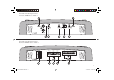
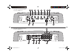
Anschlüße & Bedienungselemente Frontseite AXTON C109 11 1 12 5 2 4 3 14 13 Anschlüße & Bedienungselemente Rückseite AXTON C109 6 7 8 9 10 5 C109-509 Manual DEF.indd 5 15.02.
B1ANSCHLÜSSE & BEDIENUNGSELEMENTE C109 1 INPUT L+R Cinch-Eingangsbuchsen links und rechts zum Anschluß an die NF / Pre-Out Signal-Ausgänge des Steuergerätes. 2 INPUT GAIN Eingangsempfindlichkeitsregler zur Anpassung des Verstärkers an die Ausgangsspannung des Steuergerätes. 3 LPF REGLER Regler zum Einstellen der gewünschten Lowpass (LPF) Übergangsbzw. Trennfrequenz an der integrierten elektronischen Frequenzweiche zwischen 10 Hz und 300 Hz.
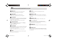
Anschlüße & Bedienungselemente Frontseite AXTON C209 und C409 12 11 1 2 3 4 5 Anschlüße & Bedienungselemente Rückseite AXTON C C209 und C409 6 7 8 9 10 7 C109-509 Manual DEF.indd 7 15.02.
B2ANSCHLÜSSE & BEDIENUNGSELEMENTE C209/C409 1 INPUT L+R Cinch-Eingangsbuchsen links und rechts zum Anschluß an die NF / Pre-Out Signal-Ausgänge des Steuergerätes. 2 INPUT GAIN Eingangsempfindlichkeitsregler zur Anpassung des Verstärkers an die Ausgangsspannung des Steuergerätes. 3 LPF REGLER Regler zum Einstellen der gewünschten Lowpass (LPF) Übergangsbzw. Trennfrequenz an der integrierten elektronischen Frequenzweiche zwischen 40 Hz und 240 Hz.
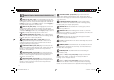
Anschlüße & Bedienungselemente Frontseite AXTON C509 10 1 4 5 6 7 3 4 8 9 Anschlüße & Bedienungselemente Rückseite AXTON C509 11 2 16 12 13 14 15 17 9 C109-509 Manual DEF.indd 9 15.02.
B3 ANSCHLÜSSE & BEDIENUNGSELEMENTE C509 1 INPUT L+R (1CH/ 2CH) Cinch-Eingangsbuchsen links und rechts zum Anschluß an die NF/Pre-Out (Front) Signal-Ausgänge des Steuergerätes, wenn die entsprechenden Lautsprecher entweder im Fullrange/Vollbereichs-, im Lowpass/Tiefpass- oder im Highpass/ Hochpass-Betrieb angesteuert werden sollen.
C MONTAGE-TIPS 1 Die Plazierung Ihres Verstärkers hat einen großen Einfluß auf die Ableitung der im normalen Betrieb entstehenden Wärme bzw. auf das eventuelle Ansprechen der automatischen Überhitzungssicherung des Gerätes. Aufgrund der Wärmeentwicklung des Verstärkers sollten Sie einen gut belüfteten Installationsort auswählen. Ideal für die Langzeitstabilität Ihres Verstärkers ist grundsätzlich jeder Montageort, an dem Luft ungehindert an den Kühlrippen vorbeiziehen kann.
Verwenden Sie die empfohlenen Stromkabelquerschnitte (siehe E). Zu geringe Querschnitte verringern die Ausgangsleistung, bewirken Verzerrungen und evtl. zu frühes Ansprechen der Übertemperatur-Sicherung. 4 Sichern Sie die +12V-Hauptleitung von der Batterie zum Verstärker ca. 20-30 cm nach der Batterie mit einer Hauptsicherung ab und verwenden Sie unbedingt Stromkabel mit leistungsbezogenem Querschnitt (Einzelheiten dazu finden Sie unter Abschnitt F: Anschluss und Einstellungen).
E ANSCHLUSS ACHTUNG: DAS +12V KABEL MUSS VOR BEGINN DER ANSCHLUSSARBEITEN UNBEDINGT VOM PLUSPOL DER BATTERIE ENTFERNT WERDEN! Empfohlene Stromkabel-Querschnitte für +12V und Masse (bei ca.
F ANSCHLUSS-VARIANTE 1+2 C209/C409 Stereo/Mono-Betrieb C209/C409 HINWEIS! ● Die AXTON Verstärker C209 und C409 können wahlweise im FULLRANGE-, HOCHPASS- oder TIEFPASS-Betrieb eingesetzt werden. ● Bei Stereo Betrieb sind Lautsprecher-Impedanzen von 2-4 Ohm erlaubt. ● Bei Mono-Brücken-Betrieb darf die Impedanz von 4 Ohm nicht unterschritten werden.
F ANSCHLUSS-VARIANTE 3 C509 HINWEIS! • Min. Lautsprecher-Impedanz für alle Kanäle 2 Ohm! • Eine Hauptsicherung mit entsprechendem Wert (nicht im Lieferumfang enthalten) muß innerhalb 30 cm von der Batterie eingesetzt werden! 2 Pre-Out 4-Kanal-Betrieb C509 15 C109-509 Manual DEF.indd 15 15.02.
F ANSCHLUSS-VARIANTE 4 C509 HINWEIS! • Min. Lautsprecher-Impedanz für alle Kanäle 2 Ohm! • Eine Hauptsicherung mit entsprechendem Wert (nicht im Lieferumfang enthalten) muß innerhalb 30 cm von der Batterie eingesetzt werden! 1 Pre-Out 3-Kanal-Betrieb C509 HINWEIS! ● Min. Lautsprecher-Impedanz für alle Kanäle min.
F ANSCHLUSS-VARIANTE 5 C509 + C109 Multi-Amp Mehrkanal-Betrieb 100 A C509 HINWEIS! ● Min. Lautsprecher-Impedanz für C209/C409/C509 in Stereo Mode ist 2-4 Ohm! ● Auch bei Mono-Brücken-Betrieb müßen beide Eingänge (L&R) belegt sein (gegebenenfalls Y-Adapter verwenden)! ● Eine Hauptsicherung mit entsprechendem Wert (nicht im Lieferunfang enthalten) muß innerhalb 30 cm von der Batterie eingesetzt werden! C109 17 C109-509 Manual DEF.indd 17 15.02.
G EINSTELLUNGEN Reihenfolge der Einstellungen Je nach Verstärker-Typ (Mono, 2-Kanal, 4-Kanal oder eine Kombination davon) oder Betriebsart (Fullrange, Hoch- oder Tiefpass) und Benützung der Lautsprecher-Ausgänge (stereo oder mono gebrückt) kann es sein, daß Sie nur Teile der in diesem Abschnitt erklärten Einstellungen benötigen. Wenn Sie Ihren Verstärker also im traditionellen Fullrange- bzw. Vollbereichsbetrieb einsetzen, können Sie die Erklärungen unter "1.
Mit der Einstellung des HIGHPASS/Hochpass-Filters (HPF) der SatellitenLautsprecher an den entsprechenden (FILTER) FREQ. Reglern soll eine elektrische und mechanische Entlastung der eingesetzten Koax- oder Kompo-Systeme erreicht werden. Je nach vorhandener Membranfläche und Nennbelastbarkeit der Lautsprecher empfiehlt sich eine Einsatzbzw. Trennfrequenz zwischen 40 und 240 Hz. Satelliten-Grundregel 1 Das klanglich hochwertigere Satelliten-System sollte immer vorne eingebaut werden.
EMPFINDLICHKEITS-ANPASSUNG UND 2 SYSTEM-ABGLEICH LEVEL Die richtige Eingangsempfindlichkeits-Einstellung ist wichtig für die Erreichung des optimalen Dynamikspielraumes Ihrer gesamten CarAudio-Anlage. Nicht optimale Anpassungen haben entweder einen überhöhten Rauschanteil oder verminderte Maximallautstärke und unnötige Verzerrungen zur Folge. Es empfiehlt sich die GAIN-Einstellungen in der nachstehenden Reihenfolge vorzunehmen: ™ Bringen Sie alle Klangregler (Bass, Mid, Treble und evtl.
H STÖRUNGSBEHEBUNG Problem Ursache Kein Musiksignal auf den Lautsprechern und Status-LED leuchtet nicht ● ● ● ● ● ● ● + 12 V oder GROUND (Masse) oder “Remote“-Kabel nicht (richtig) angeschlossen Sicherung des Verstärkers durchgebrannt Hauptsicherung an der Batterie durchgebrannt Kurzschluß auf einem der Lautsprecherausgänge DC/Gleichspannung am Ausgang Überlastung des Verstärkers Überhitzung des Verstärkers Ein Sirren das mit der Motordrehzahl zu- oder abnimmt ● ● Schlechter Masseanschluß des Verst
I TECHNISCHE DATEN AXTON C109 C209 C409 C509 Sinusleistung stereo (an 13.8V) an 4 Ohm (W RMS) min. 1 x 300 2 x 60 2 x 120 4 x 60 Sinusleistung stereo (an 13.8V) an 2 Ohm (W RMS) min. 1 x 420 2 x 95 2 x 180 4 x 90 n. a. 1 x 180 1 x 350 2 x 190 10 - 30'000 10 - 30'000 10 - 30'000 10 - 30'000 < 0.05 < 0.05 < 0.05 < 0.05 Sinusleistung gebrückt (at 13.8V) an 4 Ohm (W RMS) min.
C109-509 Manual DEF.indd 23 15.02.
Introduction Thank you for purchasing this AXTON quality audio component. The AXTON automotive amplifier series has been developed for the use with mobile sound systems using 12 Volts negative chassis ground power supply. The amplifiers may be used in combination with almost any brand and type of head unit and speakers in cars, vans, boats etc. and when installed correctly, AXTON amps will produce exceptional sound results.
Connections & Controls FRONT-PANEL AXTON C109 11 1 12 5 2 4 3 14 13 Connections & Controls REAR-PANEL AXTON C109 6 7 8 9 10 25 C109-509 Manual DEF.indd 25 15.02.
B1 CONNECTIONS AND CONTROLS AXTON C109 1 INPUT L+R Low-level RCA signal input for connection to head-unit pre-out. 2 INPUT GAIN Input gain/sensitivity control allowing the matching of the amplifier input section to the head-unit (pre-out) output voltage. 3 FILTER FREQ. LPF Crossover filter frequency control allowing the setting of the Lowpass cut-off frequency between 10 and 300 Hz.
Connections & Controls FRONT-PANEL AXTON C209 and C409 12 11 1 3 2 4 5 Connections & Controls REAR-PANEL AXTON C209 and C409 6 7 8 9 10 27 C109-509 Manual DEF.indd 27 15.02.
B2 CONNECTIONS AND CONTROLS AXTON C209/C409 1 INPUT L+R Low-level RCA signal input for connection to head-unit pre-out. 6 FUSE Fuses for protection of the amplifier-internal electronics against overload or faulty operation / wrong manipulation. 2 INPUT GAIN Input gain/sensitivity control allowing the matching of the amplifier input section to the head-unit (pre-out) output voltage. 3 FILTER FREQ.
Connections & Controls FRONT-PANEL AXTON C509 10 1 4 5 6 3 7 4 8 9 Connections & Controls REAR-PANEL AXTON C509 11 2 16 12 13 14 15 17 29 C109-509 Manual DEF.indd 29 15.02.
B3 CONNECTIONS AND CONTROLS AXTON C509 1 INPUT L+R (1CH/2 CH) Low-level RCA signal input for connection to head-unit (Front) printout for a speaker pair that will be either driven in Fullrange or Highpass amplifier mode. 2 INPUT L+R (3CH/ 4CH) Low-level RCA signal input for connection to head-unit (Rear) pre-out for a speaker pair or a subwoofer that will be either driven in Fullrange or Lowpass amplifier mode.
C AMPLIFIER LOCATION & MOUNTING The mounting location of the power amplifier will have a large effect both on its ability to dissipate the heat generated during normal operation through the heat sink and on the possible triggering of its internal overheat protection shut-off circuit. Any mounting position allowing for a good air stream across the cooling fins of the amplifiers heatsink will improve cooling and long-term stability dramatically.
Make sure you are using a main fuse protection for the +12Vpower input of the amplifier within max. 30 cm of the car battery and power cables with an amperage adequate cross-section and main fuse (for details see section E: „Connecting“). 5 The GROUND/GND cable (-12V) should have the same crosssection as the +12V power cable. Make sure to get a good chassis ground contact, because poor ground contacts are the cause for most power problems with car audio installations.
E CONNECTINGC109/C209/C409/C509 IMPORTANT: DISCONNECT THE +12V MAIN POWER CABLE FROM YOUR CAR BATTERY BEFORE ANY CONNECTING WORK IS CARRIED OUT! 3 4 Remote lead connection from head-unit to amplifier. Speaker cables to respective speakers or passive crossovers. Make sure to maintain polarity! " " to " " and " " to " ". For Mono 1-channel mode use of 4/2-channel models, connect the two terminals " " and " " marked with BRIDGE! Min.
CONNECTING DIAGRAM 1+2 C209 / C409 Stereo/Mono Operation C209/C409 Please note! ● The AXTON C209 and C409 amplifier models may be used in FULLRANGE, HIGHPASS or LOWPASS mode. ● In stereo operation speaker impedance may be 2-4 Ohms. ● In bridged mono operation minimum speaker impedance is 4 Ohms.
CONNECTING DIAGRAM 3 C509 2 Pre-Out 4-Channel Operation Please note! ● Min. speaker impedance all channels 2 Ohms! ● A main fuse (not included) of appropriate amperage must be installed within 30 cm of the car battery! C509 35 C109-509 Manual DEF.indd 35 15.02.
CONNECTING DIAGRAM 4 C509 1 Pre-Out 3-Channel Operation C509 Please note! ● Min. speaker impedance all channels min. 2 Ohms! ● For mono operation/bridged output both inputs (L&R) must still be used (if necessary use Y-adaptors)! ● A main fuse (not included) of appropriate amperage must be installed within 30 cm of the car battery! 36 C109-509 Manual DEF.indd 36 15.02.
Multi-Amp Multi-Channel Operation CONNECTING DIAGRAM 6 C509 + C109 100 A C509 Please note! ● C509 any operating mode: min. impedance 2 Ohms! ● A main fuse (not included) of appropriate amperage must be installed within 30 cm of the car battery! C109 37 C109-509 Manual DEF.indd 37 15.02.
G CONTROLS & ADJUSTMENTS Sequence of Adjustments Depending on amplifier type (mono, 2-channel, 4-channel or a combination thereof), amplification mode (fullrange, highpass or lowpass) and connecting mode (stereo or mono bridged) it is possible, that only part of the adjustments described in this manual section are applicable to your individual car audio system. If you are using your amplifier in conventional fullrange mode (eg. with a soundboard), you may skip paragraph "1.
The "Loudness" function should also be deactivated. The HIGHPASS filtering setting (HPF) - on the respective (FILTER) FREQ. control - of the satellite channels will also take away unnecessary mechanical and electrical 'strain' from coaxial speakers or component speaker systems (compos), as such speakers are not designed to reproduce powerful bass signals in the first place.
Adjustments and 2 Sensitivity Gain Matching To reach a maximum of dynamic response from your individual head unit / amplifier / speaker combination, it is important to set the respective input sensitivity controls (GAIN) correctly. Firstly the sensitivity determines the actual signal-to-noise ratio. Secondly, the sensitivity also controls the maximum distortion-free sound pressure level (SPL) possible with your specific car audio system.
H TROUBLESHOOTING Problem Cause No music signal on loudspeakers and STATUS-LED on amp is off ● + 12 V and/or GROUND (GND/ -12V) and/or “Remote” line not (properly) connected ● Fuse on amplifier or distributor blown ● Main Fuse on car battery side blown ● Short-circuit on any of the speaker outputs ● DC voltage at speaker outputs ● Amplifier overload ● Amplifier overheated A high-pitched buzzing sound in- or decreasing with engine speed ● Bad ground (GND) conntact of amplifier or head unit ● Insuffici
I SPECIFICATIONS AXTON C109 C209 Rated power output stereo (at 13.8V) at 4 Ohms (W RMS) min. 1 x 300 Rated power output stereo (at 13.8V) at 2 Ohms (W RMS) min. 1 x 420 Rated power output bridged (at 13.8V) at 4 Ohms (W RMS) min. Frequency response (Hz) Total Harmonic Distortion (THD) at 4 Ohms (%) Signal to noise ratio (dB) Channel separation (dB) Crossover slope (dB/oct) Crossover range low/highpass state-variable (Hz) HPF od. LPF Recommended power cable cross-section with approx.
Introduction Merci d’avoir acheté cet amplificateur AXTON Cette gamme d’amplificateurs a été spécialement développée pour une utilisation en milieu automobile utilisant une alimentation 12 v avec masse au châssis. Ces amplificateurs peuvent être utilisés en combinaison avec tout autre composant audio disponible sur le marché tant au niveau hautparleurs que sources. Installés correctement, les appareils AXTON vous procureront un niveau de reproduction sonore exceptionnelle.
Connections et réglages Face avant AXTON C109 11 1 12 5 2 4 3 14 13 Connections et réglages Face avant AXTON C109 6 7 8 9 10 44 C109-509 Manual DEF.indd 44 15.02.
B1 CONNECTIONS ET RÉGLAGES C109 1 ENTRÉES L+R: entrées RCA bas niveau à connecter à la source. 2 GAIN D’ENTRÉE: Permet d’ajuster au mieux les différents niveaux d’entrée. 3 FILTRE PASSE-BAS: Permet d’ajuster la fréquence du filtre passe-bas entre 30 et 300 Hz. 4 SELECTION DU MODE DE FILTRAGE: 5 FILTRE SUBSONIC: permet d‘ajuster la fréquence du filtre subsonic entre 10 et 60 Hz. 6 FUSIBLE: protége l’amplificateur contre les surcharges. 10 SORTIES: bornier haut parleur. Impédance mini: 2 ohms.
Connections et réglages Face avant AXTON C209 et C409 12 11 1 2 3 4 5 Connections et réglages Face avant AXTON C209 et C409 6 7 8 9 10 46 C109-509 Manual DEF.indd 46 15.02.
B2 CONNECTIONS ET RÉGLAGES C209/C409 1 ENTRÉES L+R: entrées RCA bas niveau à connecter à la source. 2 GAIN D’ENTRÉE: Permet d’ajuster au mieux les différents niveaux d’entrée. 3 FILTRE PASSE-BAS : Permet d’ajuster la fréquence du filtre passe-bas entre 40 et 240 Hz 7 +12 V: à connecter à la borne positive de la batterie. 8 REMOTE: signal de mise en marche de l’amplificateur, à connecter à une sortie télécommandée de la source.
Connections et réglages Face avant AXTON C509 10 1 4 5 6 7 3 4 8 9 Connections et réglages Face avant AXTON C509 11 2 16 12 13 14 15 17 48 C109-509 Manual DEF.indd 48 15.02.
B3 CONNECTIONS ET RÉGLAGES C509 1 ENTRÉES L+R CH 1/2: entrées RCA avant bas niveau à connecter à la source. 2 ENTRÉES L+R CH 3/4: entrées RCA arrière bas niveau à connecter à la source.
C PLACEMENT DE L’AMPLIFICATEUR L’emplacement de l’amplificateur dans le véhicule a une grosse incidence sur sa capacité à dissiper la température qu’il génère lors de son fonctionnement. Il peut en résulter un enclenchement excessif de la protection thermique. La position d’installation doit permettre une bonne circulation de l’air au travers des ouies d’aération. 1 Pour les amplificateurs AXTON, la meilleur position pour la ventilation est: amplificateur installé debout.
Il est impératif de placer un fusible principal au maximum à 30 cm de la batterie. L’ampérage de ce fusible est déterminé par la consommation de l’installation globale. (voir chapitre E) 5 Le câble de masse (GND) doit être de même section que le câble positif ( il y circule le même courant). Le point de masse sur le châssis doit être le meilleur possible et bien nettoyé pour assurer un bon contact électrique.
3 4 connectez le câble de remote connectez les câbles des haut-parleurs en respectant bien les polarités. Les haut-parleurs doivent avoir une impédance mini de 2 ohms !!! connectez le câble de masse qui devra être le plus court possible, enlevez bien toutes traces de peintures et de graisses à l’endroit de la connection. Au cas ou aucun point ne convienne, tirez un câble directement à la borne négative de la batterie.
1 Règle 1: Les haut-parleurs de meilleur qualité sont installés à l’avant du véhicule Règle 2: en se basant sur des haut-parleurs de diamètres et de qualité identiques, la fréquence de coupure des hps avant sera toujours réglée plus bas que la fréquence de coupure du filtre passe-haut des hps arrières. RÉGLAGE DES FILTRES INTÉGRÉS La première opération à effectuer avant même de régler les gains est de sélectionner les bonnes solutions de filtrage.
2 RÉGLAGES DE LA SENSIBILITÉ DU SYSTÈME Afin d’obtenir le maximum de réponse dynamique de votre source/ amplificateur/configuration des hauts parleurs, il est important de régler correctement les différents niveaux de sensibilité d’entrée (niveau, LEVEL). D’une part, la sensibilité détermine le niveau du rapport signal/bruit. D’autre part, la sensibilité contrôle aussi le niveau maximum de son hors distorsion permis par votre système audio embarqué.
H DÉFAUTS / SOLUTIONS Problème Cause Pas de musique, Voyant sur l’amplificateur éteint. ● ● ● ● ● Parasites aigus en rythme avec Le moteur ● mauvaise masse sur l’amplificateur et/ou l’autoradio. ● câble RCA de mauvaise qualité (blindage insuffisant).
I SPÉCIFICATIONS AXTON AMPLIFICATEUR C109 C209 C409 C509 Puissance de sortie @ 13.8V Stéréo @ 4 ohms W rms 1 x 300 2 x 60 2 x 120 4 x 60 Puissance de sortie @ 13.8V Stéréo @ 2 ohms W rms 1 x 420 2 x 95 2 x 180 4 x 90 Puissance de sortie @ 13.8V Mono @ 4 ohms W rms n. a. 1 x 180 1 x 350 2 x 190 10 – 30'000 Hz 10 – 30'000 Hz 10 – 30'000 Hz 10 – 30'000 Hz < 0.05 % < 0.05 % < 0.05 % < 0.05 % > 95 dB > 95 dB > 95 dB > 95 dB n. a.
C109-509 Manual DEF.indd 57 15.02.
C109-509 Manual DEF.indd 58 15.02.
WARRANTY CERTIFICATE Please keep this Warranty Certificate along with the sales slip/proof of purchase. Limited Warranty This AXTON product is fully warranted against defective materials or workmanship for a period of 2 YEARS from date of purchase at retail. Warranty will only be granted if the warranty certificate is presented fully completed with model, serial number (if applicable), purchaser´s address, purchasing date and dealer stamp together with the original sales slip or proof of purchase.
GARANTIEKARTE Bitte bewahren Sie diese Garantiekarte zusammen mit Ihrer Kaufbestätigung auf. Garantiebestimmungen AXTON gewährleistet auf das in dieser Karte aufgeführte AXTON-Produkt für den Fall von Material- oder Herstellungsfehlern 2 Jahre Garantie beginnend ab Kaufdatum im Fachhandel. Garantieansprüche können nur mit einer korrekt und vollständig ausgefüllten Garantiekarte zusammen mit dem Original-Kaufbeleg geltend gemacht werden.