Ayre AX-5 Owner’s Manual Integrated Amplifier
Table of Contents Welcome to Ayre . . . . . . . . . . . . . . . . . . . . . . . 2 Connections and Installation . . . . . . . . . . . . . . . . . . . . 3 Setup and Configuration . . . . . . . . . . . . . . . . . . . 7 Controls and Operation . . . . . . . . . . . . . . . . . . . . 10 Optimization and Customization . . . . . . . . . . . . . . . . . . 17 Numbers and Specifications . . . . . . . . . . . . . . . . . . 28 In Case of Trouble . . . . . . . . . . . . . . . . . . . . .
Welcome to Ayre To our North American customers, please be sure to mail your warranty registration card and photocopy of your original sales receipt within 30 days in order to extend the warranty to five years. Your Ayre AX-5 offers a significant advance in the musical performance of high-fidelity equipment. The warmth and immediacy of a live performance are apparent from the first listening.
Connections and Installation The Ayre AX-5 is easy to use. The following guidelines will ensure that the installation goes smoothly. As shipped from the factory, none of the inputs are activated. The desired inputs are activated by assigning them names as described in the following chapter, “Setup and Configuration”. Location Do not stack the Ayre AX-5 directly with other components, as this may restrict the air flow or induce hum into the audio circuitry.
Inputs When you have a choice, a balanced connection will offer slightly higher sound quality than a single-ended connection. The Ayre AX-5 offers four pairs of balanced inputs and two pairs of single-ended inputs. Balanced connections are made via three-pin XLR connectors, while single-ended connections are made with RCA connectors. In this modern era of diverse source components, it has become impractical to pre-label the inputs with the actual name of the source.
Do not connect the loudspeaker outputs to any speaker switch-box, accessory, or test equipment that has a common ground connection. Tape Outputs The Ayre AX-5 provides tape outputs, allowing connection of the selected source component to a recording device or headphone amplifier. The tape outputs utilize balanced XLR connectors. Should it be necessary to connect a tape output to a single-ended component, high-quality adapters are available from your Ayre dealer.
AC Power The AX-5 may be plugged directly into an unswitched wall outlet. Although proprietary RFI (radio-frequency interference) filtering is built into the amplifier, in some situations an AC power-line filter (such as those offered by Ayre) may provide additional sonic benefits. Break-In 100 to 500 hours of music played through the system will ensure full break-in.
Setup and Configuration Due to the large number of available inputs (six) on the AX-5, activating only the desired inputs allows for simpler operation of the unit. If no inputs are activated, the amplifier will automatically enter the setup mode when AC power is applied. Only the active inputs will be included in the list of available source components. Activating Inputs (Basic Setup Menu) The desired inputs are activated simply by naming them.
OFF INx PC CD PH DVD SCD SSP DIG TNR AUX D/A DAT CDR CBL TV VCR LD DX5 C5X QB9 CX7 DX7 D1X EX 8 X X X X X X X X X X X X X X X X X X X X X X X X SU Refer to your notes describing which source components are connected to which numbered input. Use the right-hand knob to scroll to the desired numbered input (“OFF 1” through “OFF 6”). When you have reached the desired input number, use the left-hand knob to scroll through the list of available names (shown at the left).
Re-Entering Basic Setup Mode SET UP XXX 1 To re-enter the basic setup mode to make changes to the names of inputs, make sure that the amplifier is in the low-power consumption state (right-hand pushbutton lit green—please refer to the chapter “Controls and Operation” for additional information). Then press and hold the left-hand button for three seconds. The front panel will then display “SET UP” briefly, and then“XXX 1” where “XXX” is the name assigned to input 1.
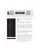
Controls and Operation Included with the Ayre AX-5 is a remote-control handset. Illustrations of the controls on the amplifier are shown to the far left, and the buttons on the remote handset are on the near left. On/Off (1/0) The main power switch for the AX-5 is a rocker at the top center of the rear panel. This switch disconnects the unit completely from the AC power. When the amplifier is turned “off” none of the auxiliary functions (e.g.
Volume Control The volume level may be controlled with either the right-hand knob or the remote-control handset, displaying the volume setting on the front panel. There are 46 individual levels, each with a step size of 1.5 dB, allowing for precise selection of the desired volume setting. If the volume control is advanced beyond the highest available level, the front panel will briefly display the message “MAX”.
AX-5 to “zero” while retaining the current volume setting in memory. Pressing either button a second time restores the volume to the previous level. When the mute function is activated, all five decimal points in the display will light up. Low-Power Consumption Mode Press and hold the right-hand front-panel button for three seconds (or a short press of the “1/0” remote button) to enter the low-power consumption mode.
Tape Outputs/Basic Setup Mode The left-hand button on the AX-5 activates two functions—the tape outputs and the basic input setup mode. Tape Outputs The tape outputs may be controlled either by the left-hand button on the front panel, or from the remote handset. Pressing the button activates the tape outputs, and pressing it a second time will turn them off. When the tape outputs are activated, the red LED in the front-panel switch is illuminated.
Display Brightness The brightness of the front-panel display may be controlled via the remote control. There are three brightness levels and a “display off” setting. Each press of the remote control button scrolls through the four available brightness settings. A small blue light indicates that the display is turned off.
Disc Player Configuration As shipped from the factory, the remote control handset is configured to operate the Ayre C-5xeMP disc player. The button with three horizontal lines operates the “Audio” function that selects between various soundtracks on a DVD disc. Please refer the C-5xeMP Owner’s Manual for additional details.
The remote handset may also be easily configured MP to operate either the Ayre CX-7e CD player, MP C-5xe Stereo Universal player, or DX-5 Universal A/V Engine, which each use different command sets. Please refer to the chapter “Optimization and Customization” for details.
Optimization and Customization In most audio systems, the AX-5 amplifier only requires that the desired inputs be activated by naming them. Each source component is clearly identified and only the connected inputs are displayed in the list of available source components. This is the basic setup mode. In certain installations it may be desirable to customize additional settings for each input by using the advanced setup mode.
SET UP XXX 1 CN GOS PP AL RST To enter the advanced setup mode, make sure that the amplifier is in the low-current consumption state (green LED illuminated on the right-hand button). Then press and hold the left-hand button for three seconds. This enters the unit into the basic setup mode. The display will briefly show “SET UP” and then display “XXX 1” where “XXX” is the name assigned to input 1. Use the right-hand knob to select which input (1 - 6) you wish to configure with advanced options.
Custom Name A custom name (up to 3 characters) may be created as follows: 1) From the advanced set up menu, rotate the left-hand knob to scroll to the selection “ CN”. 2) Press the right-hand button to enter the next menu level. The current name will be displayed, with the selected character designated with a decimal point (cursor) after the character. The left hand knob selects the cursor position. 3) Use the right-hand knob to select the desired character.
GOS GOS GOS GOS GOS 0.0 1.5 3.0 4.5 6.0 The gain offset offers an adjustment from +0 dB to +6 dB in 1.5 dB increments. Therefore the source components with lower output levels may be boosted to match the source components with higher output levels. Once you have selected the “GOS” menu item with the left-hand knob, simply select the desired offset level with the right-hand knob. Changing the gain offset from +0 dB will affect the maximum displayed volume level.
The chosen input is now programmed for Processor Pass-Through operation, disabling the now redundant volume control of the AX-5. When that input is selected, the AX-5 is set to the standard power amplifier gain (26 dB), and the volume is controlled directly from the surround-sound processor. The volume indicator of the AX-5 will display “PP” to show that the Processor Pass-Through mode has been selected for that input.
However, in certain extremely rare situations, it is possible that the AyreLink communication system will require adjustments to the configuration settings. To gain an understanding of these circumstances, it is necessary to understand how the AyreLink automatically selects the correct input on the AX-5. When any AyreLink source component is turned on, it broadcasts that information to the other linked components.
In this case there is no default AyreLink code that would select this input. To address these issues, the setup menu allows each named input to be associated with an AyreLink identification code. Once you have selected the “ AL” menu item with the left-hand knob, simply select the desired identification code (“ A” to “Z”, or “_” for “none”) with the right-hand knob. ALA . . ALZ Do not assign any single identification code to more than one input. Improper operation may result.
Overall Gain The volume control for the AX-5 amplifier comprises a 69 dB range. For most audio systems this will provide more than enough range, allowing for low-level late-night listening sessions as well as the ability to totally immerse yourself in your favorite music at high volumes. If you need to change the overall gain of your system, please contact your Ayre dealer.
easily configured to operate an Ayre CX-7eMP CD player (or other disc player that utilizes the RC-5 remote control protocol), or also an Ayre DX-5 Universal A/V Engine. To change the remote control handset to operate the CX-7eMP, simply press the number button “7” five times in succession. (Please note that the “Audio” button used to select soundtracks on DVD discs will have no function in this configuration.
then in turn control amplifiers linked by the AyreLink communications system. Connect the AyreLink ports of your components in a daisy-chain fashion as described in the chapter “Connections and Installation” with the AX-5 at one end of the chain. The unused AyreLink port on the amplifier is then used as a trigger input. Rear view of AX-5 amplifier. An adapter cable must be fabricated to connect the trigger output of the control component to the AyreLink port of the AX-5 amplifier.
During level-sensitive operation, applying a voltage to the trigger input will set the amplifier to the “Operate” mode. When the applied voltage drops to zero, the unit reverts to the low-power consumption mode. In the pulse-sensitive mode, a positive-going pulse will toggle the amplifier between the low-power consumption and “Operate” states, duplicating the action of the right-hand front-panel button when it is held for three seconds.
Numbers and Specifications Power Output Maximum Input Level Input Impedance XLR Input Polarity Gain 8 V rms – unbalanced inputs 16 V rms – balanced inputs 1 MΩ – unbalanced inputs 2 MΩ – balanced inputs (1 MΩ per phase) Pin 1 = Ground Pin 2 = Non-inverting (Positive) Pin 3 = Inverting (Negative) 32 dB (maximum, at volume level of “ 46”) Frequency Response DC - 250 kHz Power Consumption 48 watts in low-current consumption mode 230 watts in operating mode, no signal Dimensions Weight 28 125 watt
In Case of Trouble The Ayre AX-5 provides comprehensive protection for both your amplifier and loudspeakers, including faults that may occur in your source components. Overheating If the unit is operated at high playback levels with insufficient ventilation, the internal temperature may become too high, triggering the thermal protection circuitry.
Rail Fuses Four internal power supply fuses protect both the loudspeakers from excessive current and the amplifier from short-circuits. If any of these fuses blows, the amplifier will not operate and the warning LED in the display will glow red. The input selector characters will change to read “FUS” when one of the internal fuses blows. The amplifier must be completely disconnected from the AC power to replace the fuses. Do not remove the amplifier cover. Hazardous voltages may exist inside the unit.
DC Offset The Ayre AX-5 incorporates a circuit to detect the presence of DC at the output terminals which could be harmful to the loudspeaker. In this situation, the warning LED in the display will glow red, the input will be muted, the bias will be removed from the output stage, and the amplifier will not operate. The input selector characters will change to read “DC” when excessive DC offset is present.
Statement of Warranty North American Warranty Your Ayre AX-5 integrated amplifier is warranted against defects in materials and workmanship for a period of ninety days from the date of original purchase. This ninety-day coverage is automatic upon acceptance of delivery and no registration is required.
North American Warranty Statement 1. If any defects are found in the materials or workmanship of this Ayre product within the warranty period, the unit will be repaired or replaced by Ayre Acoustics, Inc. (Ayre) or its authorized agent. 2. Purchaser must return the product, packed in the original shipping carton, freight prepaid to: Ayre Acoustics, Inc. 2300-B Central Avenue Boulder, Colorado 80301 or to Ayre’s authorized agent.
4. Ayre strives to manufacture the finest possible equipment, and therefore reserves the right to make improvements on its products, without necessarily assuming any obligation to retrofit such changes upon its previously manufactured models. 5. The above warranty is the sole warranty given by Ayre, and is in lieu of all other warranties. All implied warranties, including warranties of merchantability or fitness for any particular purpose shall be strictly limited to the duration of the above warranty.
A Place for Notes Serial Number: ________________________________________ Purchase Date: ________________________________________ Dealer: ________________________________________ Salesperson: ________________________________________ 35
36 Rev. 1.
Ayre Acoustics, Inc. 2300-B Central Avenue Boulder, Colorado 80301 www.ayre.