Owner’s Manual OUTDOOR PATIO HEATER MODEL # HSS-RS-TB DANGER If you smell gas: 1. Shut off gas to the appliance. 2. Extinguish any open flame. 3. If odor continues, keep away from the appliance and immediately call you gas supplier or fire department. WARNING WARNING indicates an imminently hazardous situation which, if not avoided, will result in death or serious injury. WARNING Do not store or use gasoline or other flammable vapors and liquids in the vicinity of this or any other appliance.
PACKAGE CONTENTS A B C D E F G H I J PART A B C D E F G H I J K L M N O K L M N O 2 DESCRIPTION Reflector Panel Reflector Plate Head Assembly Gas Hose Regulator Upper Deck Cover Lower Deck Cover Upper Wicker Cover Middle Wicker Cover Deck Cover Bracket Upper Pole Lower Pole Cylinder Housing Wheel Kit Base QUANTITY 3 1 1 1 1 1 1 1 1 2 1 1 1 1 1
HARDWARE CONTENTS (shown actual size) AA M8 Flange nut Qty. 2 II Bolt M8 x 15 Qty. 7 M6 Flange nut Qty. 4 Bolt M6 x 30 Qty. 6 Screw M6 X 10 Qty. 9 Cap nut Qty. 9 EE 3/16 Screw Qty. 4 LL KK JJ Washer Φ6 Qty. 9 DD CC BB Washer Φ8 Qty. 6 SAFETY INFORMATION MM FF M6 nut Qty. 2 NN Wing nut Qty. 3 Reflector spacer Qty. 3 HH GG Bolt M6 X 12 Screw M4 X 10 Stainless steel Stainless steel Qty. 4 Qty. 2 OO Philips screwdriver Qty. 1 PP Wrench Qty.
SAFETY INFORMATION DANGER DANGER • EXPLOSION - FIRE HAZARD • Keep solid combustibles, such as building materials, paper or cardboard, a safe distance away from the heater as recommended by the instructions. • Provide adequate clearances around air openings into the combustion chamber. • Never use the heater in spaces which do or may contain volatile or airborne combustibles, or products such as gasoline, solvents, paint thinner, dust particles or unknown chemicals.
SAFETY INFORMATION WARNING WARNING California Proposition 65 Combustion by-products produced when using this product contain chemicals known to the State of California to cause cancer, birth defects, and other reproductive harm. • This product is fueled by propane gas. Propane gas is invisible, odorless, and flammable. An odorant is normally added to help detect leaks and can be described as a “rotten egg” smell. The odorant can fade over time so leaking gas is not always detectable by smell alone.
ASSEMBLY INSTRUCTIONS 1. Assemble the wheel kit. Line up holes on the bracket of wheel kit with the corresponding holes on base , then insert M8 x 15 mm bolts through holes. Hand tighten with M8 flange nuts. Be sure the wheel assembly is parallel to the base. 1 O N Hardware Used AA BB M8 Flange nut Bolt M8 x 15 x2 AA BB x2 2. Assemble the cylinder housing. Attach cylinder housing to base with 5pcs M8 x 15 mm bolt and secured them. 2 M Hardware Used BB BB Bolt M8 x 15 x5 3.
ASSEMBLY INSTRUCTIONS 4. Assemble the upper pole. Insert the upper pole into the lower pole. Make sure the upper pole does not sit up side down. The up side should have four closer holes from the end. Line up the holes and secure them with 4pcs 3/16 screws. Hardware Used EE 3/16 Screw 4 K EE x4 5. Put the 2pcs M6x30 bolt through the hole of the bracket inside the middle wicker cover at the lower end, secured with 2pcs M6 nut underneath.
ASSEMBLY INSTRUCTIONS 7. Assmble the upper wicker cover. Put the upper wicker cover though the pole and push it to the end. 7 8. Put the lower deck cover through the upper wicker cover. Make sure the wider opening is facing down. Then put the upper deck cover through the upper wicker cover. Make sure the wider opening is facing up. 8 9. Insert hose of head assembly into pole. Line up the holes on head assembly to the holes on pole.
ASSEMBLY INSTRUCTIONS 10. Assemble the deck cover bracket. Secure the deck cover and bracket to the pole with 4pcs M6X12 bolts. This step also secures the head assembly to the pole. Bolt M6 X 12 J GG Hardware Used GG 10 x4 11. Secure the upper deck cover. Push the upper deck cover upwards until it is flat against the head assembly. Line up the holes on upper deck cover to the holes on deck cover bracket. Secure them with 2pcs M4 X 10 screws. 11 HH Hardware Used HH Screw M4 X 10 x2 TT 12.
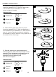
ASSEMBLY INSTRUCTIONS 13. Slide two reflector panels together. Insert one screw M6 X 10. Slide one washer Φ 6 over threaded end of screw M6 X 10 and screw on cap nut loosely. Hardware Used KK Washer Φ6 x9 JJ Screw M6 X 10 x9 KK Cap nuts x9 II 13 II JJ 14. Slide reflector plate onto reflector panels. Insert one screw M6 X 10 . Slide one washer Φ 6 over threaded end of screw M6 X 10 and screw on cap nut loosely. Repeat procedure to complete the assembly of all four sections.
ASSEMBLY INSTRUCTIONS 16. Screw the regulator to the hose. Install the gas cylinder Open the door and put the gas cylinder onto the base, then secure it with gas cylinder secure belt. And then screw the regulator to the gas cylinder contector. WARNING: Use a standard 20 lb. propane cylinder only. Use this heater only with a propane vapor withdrawal supply system. See chapter 5 of the standard for storage and handling of liquefied petroleum gas, ANS/NFPA 58.
ASSEMBLY INSTRUCTIONS A dented, rusted or damaged propane cylinder may be hazardous and should be checked by your cylinder supplier. Never use a propane cylinder with a damaged valve connection. The propane cylinder must be constructed and marked in accordance with the specifications for LP gas cylinders of the U.S. Department of Transportation (DOT) or the standard for cylinders, spheres and tubes for transportation of dangerous goods and commission, CAN/CSA-B339.
OPERATION INSTRUCTIONS Leak Check WARNING • Perform all leak tests outdoors. • Extinguish all open flames. • NEVER leak test when smoking. • Do not use the heater until all connections have been leak tested and do not leak. Hose / Regulator connection Regulator / Cylinder connection 1. Make 2-3 oz. of leak check solution (one part liquid dishwashing detergent and three parts water). 2. Apply several drops of solution where hose attaches to regulator. 3.
OPERATION INSTRUCTIONS DANGER • CARBON MONOXIDE HAZARD • For outdoor use only. Never use inside house, or other unventilated or enclosed areas. This heater consumes air (oxygen). Do not use in unventilated or enclosed areas to avoid endangering your life. Caution: Do not attempt to operate until you have read and understand all General Safety Information in this manual and all assembly is complete and leak checks have been performed. Before Turning Gas Supply ON: 1.
OPERATION INSTRUCTIONS 3. Push in gas Control Knob and turn counterclockwise to “IGNITER” then to “PILOT” (Figure b) to light the pilot. If needed, keep depressing and turning Control Knob counterclockwise until the pilot lights (You should hear 2 clicking sounds). 4. Once the pilot is lit, continue to depress the Control Knob for 30 seconds. 5. If the pilot dose not stay lit, repeat steps 3 and 4. Figure c 6.
OPERATION INSTRUCTIONS WARNING FOR YOUR SAFETY Be careful when attempting to manually ignite this heater. Holding in the control know for more than 10 seconds before igniting the gas will cause a ball of flame upon ignition. When heater is ON: Emitter screen will become bright red due to intense heat. The color is more visible at night. Burner will display tongues of blue and yellow flame.
OPERATION INSTRUCTIONS 9. Heater is away from gasoline or other flammable liquids or vapors. 10. Heater is away from windows, air intake openings, sprinklers and other water sources. 11. Heater is at least 24 in. on top and at least 36 in. on sides from combustible materials. 12. Heater is on a hard and level surface. 13. There are no signs of spider or insect nests. 14. All burner passages are clear. 15. All air circulation passages are clear. 16.
CARE AND MAINTENANCE Gas odor with extreme yellow tipping of flame. Heater does NOT reach the desired temperature. Heater glow is excessively uneven. Heater makes popping noises. Spiders and insects can nest in burner or orifices. This dangerous condition can damage heater and render it unsafe for use. Clean burner holes by using a heavy-duty pipe cleaner. Compressed air may help clear away smaller particles. Carbon deposits may create a fire hazard.
TROUBLESHOOTING PROBLEM POSSIBLE CAUSE CORRECTIVE ACTION Cylinder valve is closed Open valve Blockage in orifice or pilot tube Pilot won’t light Air in gas line Note: Heater operates Low gas pressure with cylinder valve fully open at reduced efficiency below 40ºF (5ºC) Igniter fails Clean or replace orifice or pilot tube Open gas line and bleed it (pressing control knob in) for not more than 1 - 2 minutes or until you smell gas Turn cylinder valve OFF and replace cylinder Use match to light pilot;
ONE-YEAR LIMITED WARRANTY This product is inspected, tested and carefully packaged to minimize the chance of damage during shipment. If a part (excluding light bulbs and fuses*) within one year from the date of purchase proves to be defective in material or fabrication under normal use, the part will be repaired or replaced. The Company's obligation under the warranty is to replace or repair defective parts at our discretion.