
User`s guide


18
RECEIVER SETUP
A. Powering the Receiver:
The 500UDR can be powered either by using internal batteries (#9) or from
the “DC IN” connector (#2).
To use internal batteries:
1. Remove the battery door (#10) by pressing in and down on the clip
(#10A) until the door is completely free of the unit.
2. Install 6 fresh/new Alkaline “AA” batteries following the polarity mark-
ings on the holder. DO NOT USE RECHARGEABLE BATTERIES!
3. Replace the battery door (#10).
New, fresh “AA” Alkaline batteries will last approximately 6 hours.
If the power-on LED starts to flash it is time to replace the batteries.
To use the camera’s DC Output
By using the dc input (#2) the 500UDR can accept between 9 and 12VDC @
1700mA directly from the camera or other power supply. The 4-pin connec-
tor uses pin 4 for positive (+) and pin 1 for negative (-). Pins 2 and 3 are not
used.
B. Mounting the Receiver:
To attach the 500UDR directly to the camera use the included Velcro.After
choosing an appropriate location on the camera, peel and attach the smooth
surface portion of the Velcro directly to the 500UDR (not the side with the
battery door), then attach the rough surface portion of the Velcro to the cam-
era. For best reception try to mount the 500UDR in a location that keeps the
antennas above and away from the camera body. Be sure the surfaces on
the camera and 500UDR are clean and oil free before attaching the
Velcro.
C. Attaching the Antennas:
1. To attach the antenna, fit the BNC connector on the antenna on to the
receiver (#8), press down and rotate clockwise.
2. To remove antennas, rotate the antenna’s BNC connector counterclock-
wise and pull up.
D. Connecting the Output Cable:
1. It is necessary to connect the output (#1) of the 500UDR to the ‘MIC’ or
‘LINE’ input on the camera by means of a properly wired cable (not sup-
plied). The connector on the 500UDR is wired with pin 1 as ground, pin 2
as plus (+) and pin 3 as negative (-).
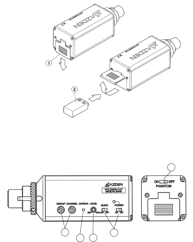
(3) Frequency select
The group knob allows you to select any of seven frequency groups (numbered from 0-6). The channel
knob allows you to select any of nine frequency channels (numbered from 0-8) within the selected group.
(4) Power and Audio switches
The power “On/Off” switch enables and disables all transmitter functions while the Audio “On/Off” switch turns
just the transmitter’s Audio signal on and off. Switching the Audio to “Off” will cause the receiver to mute using
the tone squelch circuitry in the receiver. This allows the microphone to be handled with no noise. The
“Phantom” switch allows the 51XT to provide 5V to power electret condenser microphones.
(5) Audio input LEVEL control
This enables you to adjust the input level of the microphone. Turn clockwise to increase, or counterclock-
wise to decrease the input level. A small screwdriver is supplied to make adjustments.
4
4
3
5
6
51XT plug-in XLR transmitter with 63 on-board user selectable UHF frequencies. Ideal for use with dynamic
microphones with XLR output.
(1) Open the battery compartment lid by sliding it down and raising it
(2) Insert one fresh alkaline 9-volt battery into the compartment. Make sure battery polarity is correct.