
Instruction Manual

s
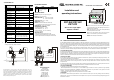
70 mm
90
45
SET
33
UP
SET
DOWNDEFROST
Led 1Led 2
Azel Technologies Inc. reserves the right to make changes without further notice to any
products herein to improve reliability, function or design. Azel Technologies Inc. does not
assume any responsibility for any improper use or application of any product or circuit described
herein. Azel Technologies Inc. products are not designed, intended, or authorized to be use as
components in systems or applications intended to support or sustain life, or for any other
application in which the failure of the Azel Technologies Inc. product could create a situation
where personal injury or death may occur.
Rev.: 05-12-2005 Cod.: 00990260
DST-900/DST-902
DST-922
One or Two stage digital
setpoint controller
Installation and
operating instructions
6.00 PARAMETER LIST
# MEANING SETTING
FACTORY
SETTING
SEt Main Set Point Range between «LoS» & «HiS» 75 °F
HYS
Thermostat main
differential (Hysteresis 1)
Range 0 .. 17.9 °F
1 °F
HY2
Thermostat secondary
differential (Hysteresis 2)
only DST-922
Range 0 .. 17.9 °F
1 °F
LoS
Minimum value for SET
POINT parameter
Range –55 .. +211 °F
-39 °F
HiS
Maximum value for SET
POINT parameter
Range -21 .. +308 °F
238 °F
Act Action main output 0: cold; 1: heat 1
Ac2
Action secondary output
only DST-922
0: cold; 1: heat
1
OFS
Offset, temperature
calibration for probe
Range –8.4 .. +7.6 °F
0
AcY
Anticycling time main
output
Range 0 .. 254 (see tis)
0
dl2
Anticycling time secondary
output
only DST-922
Range 0 .. 254 (see tis)
0 sec
dPt Defrost pause time Range 1 .. 254 (see tis)
1
ddt Defrost duration time Range 0 .. 99 (see tis) 0 (disabled)
unt Temperature displayed unit
0: Celsius;
1: Fahrenheit
1
rES Resolution
0: decimal point resolution;
1: unit resolution
1
utd Display update time delay Range 0 .. 60 sec 1 sec
tiS Defrost time scale
0: ddt minutes, dpt hours, acy/dl2 seconds;
1: ddt seconds, dpt minutes, acy/dl2 seconds;
2: ddt minutes, dpt hours, acy/dl2 minutes;
3: ddt seconds, dpt minutes, acy/dl2 minutes
0
St2
Secondary set point
only DST922
7.00
A
NOMALIES SIGNALING
MSG CAUSE OUTPUT
PF1
The probe input line is open
or short circuited.
The measured temperature is
out of range.
- output K1 will switch-off;
- output K2 does not
change.
8.00 SPECIFICATIONS
DISPLAY: 3 digit, 13.2 mm, high intensity green;
INPUTS: one PTC or NTC sensor;
MEASURING RANGE: -55 … +302 °F for PTC probe;
-39 … +248 °F for NTC probe;
FRONTAL PANEL LAYOUT AND FUNCTIONS
ACCURACY AT 25°C: ±1 °F + 1 digit;
RESOLUTION: 0.2 or 2 °F;
OUTPUTS: 1 spdt 250Vac 16A max resistive (1hp),
+ 1 spdt 250Vac 8A max resistive (0.5hp) only for DST-9x2;
POWER SUPPLY: 115 Vac ±10% 50/60Hz;
ENVIRONMENTAL CONDITIONS:
- operating temperature: –5 … +50 °C;
- storage temperature: –20 … +70 °C;
- relative humidity: 30 … 90 % non condensing;
- no shocks or vibrations;
MECHANICAL DATA:
- plastic housing self extinguishing type UL94V0;
- connections through terminal block for 2.5mm
2
gauge wire;
- protection degree: IP64 for the frontal panel (enclosure IP31).
Range between «LoS» & «HiS»
75 °F
Pt Sensor Probe Type
0: NTC (10Kohm thermistor; range –40..+248°F)
1: PTC (1Kohm thermistor; range –58..+302°F)
0
1.00 GENERAL DESCRIPTION AND INSTALLATION NOTICE
The DST-900/DST-902/DST-922 models are suitable for a wide range of applications. The DST-900 is a One Stage Digital Setpoint Control to
drive a relay in order to reach a set point temperature value. The DST-902 is also a One Stage Setpoint Control but with two relay outputs. The
DST-922 is a Two Stage Digital Setpoint Control to drive two relayes according two different temperature values. The controllers are available
with off cycle defrost (compressor switching OFF, see “ddt” and “dpt” parameters). The access to the operating parameters can be prevented
by a combination of keys.
The controller must be installed in a place protected from extreme vibration, impact, water, corrosive gases, and where temperatures and
moisture do not exceed the maximum rating levels indicated in the specifications. The same directions are valid for the probe installation.
1.10 THE THERMOSTAT PROBE
The probe must be installed in a place protected from direct air flow particularly far from fans and doors, so a better average temperature of the
room will be measured. The probe is not waterproof, it should be placed with its head upward, so that drops would not penetrate into the bulb
and damage the sensor. Maintain the length of the electrical wires as short as possible in order to keep the noise picked by them at low level,
otherwise a shielded wire will be needed, where the shield will be connected to the ground.
1.20 ELECTRICAL WIRING
We recommend to protect the power supply of the controller from electrical noise, spikes, and especially from voltage surges and drops. This
can be easily done following these recommendations:
-separate the power supply of the loads (compressor, heaters, fans, etc) from the power supply of the controller. This can alleviate problems
related to voltage dips that can arise during the switch-on of the loads, that may interfere with the controller’s microprocessor causing
unexpected resets.
-the cables of the probes and the ones of the controller supply or the loads must be separated and not close, to reduce spikes and noise on the
sensor. This improves the stability of the reading and it also makes the commutation of the device more accurate.
1.30 CRITICAL ENVIRONMENT
For applications in heavy industrial environment these rules should be followed.
- After having identified the source of noise spikes, it is recommended to apply a line filter to the source in question of the type specifically
designed to solve EMC (Electromagnetic compatibility) related problems. Sometimes it may be sufficient an RC type filter, also called
«snubber» , connected in parallel to the external relay coils, or circuit breakers.
- An independent power supply should be used to power the device in extreme conditions.
1.40 MOUNTING
The controller is a DIN rail mounting instrument which can be mounted onto the wall or panels. For easily mounting, remove the DIN rail by
sliding it out first. Use screws to mount the DIN rail onto the wall/panel. Then snap on the control to the DIN rail by pulling black trigger on the
bottom with a screw driver.
Up: 1) To increase the value of the selected parameter; 2) To
scroll the parameters in SET mode; 3) During defrost action, to
update the probe 1 temperature.
Down: 1) To decrease the value of the selected parameter; 2)
To scroll the parameters in SET mode.
Set: To access the parameter menu to view and change the
values. It is also the “Enter” key to confirm the new values.
Defrost: Used to start/stop a manual defrost.
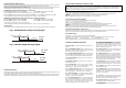
Typical terminal connections (See the label close to the terminals
for the right power supply diagram connection).
115VAC
8(3)A 250Vac
16(8)A 250Vac
K1K2
DST-902
DST-922
L
N
PUMP
(LOAD)
L(black)
(White)
N
N
L
TT
ON BOILER
PUMP
(LOAD)
16(8)A 250Vac
K1
DST-900
115VAC
L
L
N
N
L(black)
(White)
N
Azel Technologies Inc.
PO BOX 53138
10 Royal Orchard Blvd.
THORNHILL, ONTARIO
CANADA L3T 7R9
Ph: 905-764-8809
Fax: 905-764-4738
web: www.azeltec.com
e-mail: info@azeltec.com