Operating instructions OI/ADS430–EN Rev. A Aztec ADS430 Optical dissolved oxygen probe Measurement made easy Introduction For more information The ADS430 (RDO® PRO-X) probe is a rugged, reliable instrument designed to deliver accurate dissolved oxygen (DO) data across a wide measurement range using the latest optical technology for DO measurement. Publications for the associated Aztec AWT440 transmitter are available for free download from www.abb.
Contents 1 Health & Safety ..........................................................3 1.1 1.2 1.3 1.4 1.5 1.6 1.7 Document symbols ...................................................... 3 Safety precautions ....................................................... 3 Potential safety hazards ............................................... 3 1.3.1 Aztec ADS430 probe – electrical ...................... 3 Safety standards .......................................................... 3 Product symbols .............
1 Health & Safety 1.1 Document symbols Symbols that appear in this document are explained below: WARNING – Bodily injury This symbol in conjunction with the signal word 'WARNING' indicates a potentially dangerous situation. Failure to observe this safety information may result in death or severe injury. IMPORTANT (NOTE) This symbol indicates operator tips, particularly useful information or important information about the product or its further uses.
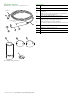
2 System overview Item Feature ADS430 probe components are shown in Fig. 2.1: A EZLink digital sensor connector B Shroud C Sensor cap (supplied unfitted in sealed factory-supplied container) Note. the sensor cap serial number is programmed on the memory chip inside the cap. D Probe body (including temperature sensor) E 10 m (39.3 ft.) fixed cable Note. The probe serial number is printed on a label at the plug end of the fixed cable.
3 Installation 4. Align arrow G on sensor cap E with index mark H on the probe. 3.1 Siting IMPORTANT (NOTE) When fitting the sensor cap, DO NOT touch the cap end. Max. 210 m (64 ft.) 5. Slide sensor cap E over probe tip D firmly until it seals over O-rings F – do not twist the cap. 6. Refit shroud A by screwing it onto probe body B. Ensure O-ring is fitted. Fig. 3.1 Siting the sensor 3.2 Probe dimensions Dimensions in mm (in.). 203 (8) 57 (2.27) 47 (1.85) Fig. 3.2 Probe dimensions 3.
3.5 Mounting / cleaning options Probe mounting / cleaning options are shown in Table. 3.
4 Sensor setup – first-time installation The following Configuration parameters are set at Easy Setup level: — — — — — — — — — — IMPORTANT (NOTE) Perform this procedure when a new / replacement sensor cap is connected to the transmitter for the first time only. For existing sensors, see Section 5, page 8. To perform a first-time installation (Easy Setup menu): 1. Connect a new or replacement probe to the transmitter’s EZLink connector – see transmitter Operating instructions OI/AWT440-EN.
5 Sensor setup 3. IMPORTANT (NOTE) Perform this procedure on existing probe(s) only. Probes are setup / configured individually. If installing a new / replacement probe, see Section 4, page 7. Ensure S1 :RDO is highlighted and press the the Select prompt). The S1 :RDO menu page is displayed: S1 :RDO Connect the ADS430 probe to the transmitter’s EZLink connector – see transmitter Operating instructions OI/AWT440-EN. 2.
5.1 Sensor Setup Menu Sensor Setup Exit Used to set the tag, measurement units, operational range and clean functions and to compensate for salinity and barometric pressure. Select Menu Comment Default S1 (to 4) :RDO Select the optical dissolved oxygen probe to set up. Tag Enter an alphanumeric probe tag (16 characters maximum) to identify the probe on the Operator Pages. PV Type Select measurement type. Note. If a change is made the I/O sources are reset.
Menu Comment Default Salinity Correction Required when monitoring water containing high quantities of dissolved salts. Enter the required value between 0 and 42 Practical Salinity Units (PSU). Leave at the default value of 0 PSU if salinity correction is not required. 0 PSU Barometric Pressure Barometric pressure compensation. Set the local barometric pressure to 506 – 1114 mbar (380 – 835 mm/Hg). If the barometric pressure is unknown, leave at the default sea-level value of 1013 mbar (760 mm/Hg).
6 Calibration This section describes how to calibrate the probe and involves measuring the probe's sensitivity to oxygen by exposing the probe to water-saturated air. Calibrations are initiated via the Cal prompt displayed on Operator pages or via the Calibrate and Advanced menu items on the Access Level page – refer to transmitter Operating instructions OI/AWT440-EN for all transmitter menu options.
6.2 1-Point calibration (water-saturated air) Referring to Fig. 6.1: 1. 2. 3. Remove storage cap A from the top of calibration chamber B . 7. At the transmitter perform a 1-point calibration from an Operator page as follows: 8. Press the key (below the Cal prompt). AWT 440 Place sponge wafer C in the bottom of calibration chamber B and saturate with approximately 10 ml (0.34 fl oz [US]) of water. 2014–08–20 10:34:52 7.62 Fit vented calibration cap D to the top of calibration chamber B .
15. When span calibration is complete, a results page is displayed: 11. If 1-Point Cal is displayed, go to step 14. If 1-Point Cal is not displayed, press the (below the Edit prompt). key The Calibration Type selection page is displayed: Calibration Type 2-Point Cal 99.98 % 24.90 °C 0.045 1.054 Exit Cancel OK / PV Tmp Offset Slope 1-Point Cal 12. Use the press the Calibrate keys to select 1-Point Cal and key (below the OK prompt).
6.3 2-Point calibration (100 % and 0 % saturation) IMPORTANT (NOTE) — Do not leave the probe in the calibration chamber for more than 30 minutes – this can allow condensation to form on the surface of the sensing element, producing false low readings after calibration. IMPORTANT (NOTE) This calibration procedure requires 60 ml (2.0 fl oz [US])) of fresh sodium sulphite solution. 1. Perform a 1-point calibration.
11. Use the / keys to select the probe to be calibrated and press the key (below the Select prompt). 15. Press the key (below the Continue prompt). The Calibrate page is displayed: Calibrate The Calibration Type page is displayed: PV Tmp S1 :RDO 99.98 % 25.22 °C Calibration Type 2-Point Cal Settling-Please Wait Abort Next 16. When span calibration is complete, the Calibrate / Start Zero Cal? page is displayed: Edit 12. If 2-Point Cal is displayed, go to step 14.
21. Press the key (below the Continue prompt). The Calibrate page is displayed: Calibrate PV Tmp 2.31 % 25.31 °C 6.5 Calibration timings Settling-Please Wait Abort 22. When zero calibration is complete, a results page is displayed: 2.31 % 25.40 °C Offset Slope 0.041 0.954 6.6 Calibration troubleshooting – slow sensor calibration or no response to dissolved oxygen changes 1. Check probe configuration / recalibrate probe – refer to Section 6, page 11. Exit 23. Press the 6.5.
7 Maintenance 7.1 Cleaning the sensor cap 1. Isolate the transmitter and remove the probe from the process. Referring to Fig. 7.1: 2. Unscrew shroud A from probe body B. 3. Rinse sensor cap C with clean water from a spray bottle. 4. Gently wipe sensor cap C with a soft-bristled brush or, if biofouling is present, a soft cloth. If necessary, use a grease remover to remove grease. 5. Refit shroud A by screwing it onto probe body B. 7.3 Cleaning the probe body 1.
8 Specification Power Sensor type Consumption (maximum) 50 mA @ 12 V DC Optical (luminescent) dissolved oxygen sensor Probe Measurement current 6 mA typical @ 24 V DC IP rating IP68 Idle current (no measurement or consumption) 160 μA typical @ 24 V DC Range 0 to 50 mg/l concentration; 0 to 600 % saturation Cable Accuracy ±0.1 mg/l, 0 to 8 mg/l ±0.2 mg/l, 8 to 20 mg/l ±10 % of reading, 20 to 50 mg/l Resolution 0.
9 Spares and accessories Acknowledgements 9.1 Spares RDO is a registered copyright of In-Situ Inc. Part number Description ADS430203 ABB RDO probe O-ring replacement kit ADS430204 ABB RDO probe sensor cap replacement kit ADS430205 ABB RDO probe calibration kit ADS430212 Nose replacement kit AWT4009010 1 m (3.2 ft.) extension cable AWT4009050 5 m (16.4 ft.) extension cable AWT4009100 10 m (32 ft.) extension cable AWT4009150 15 m (49.2 ft.) extension cable AWT4009250 25 m (82 ft.
ABB Inc. Process Automation 125 E. County Line Road Warminster PA 18974 USA Tel: +1 215 674 6000 www.abb.com Note We reserve the right to make technical changes or modify the contents of this document without prior notice. With regard to purchase orders, the agreed particulars shall prevail. ABB does not accept any responsibility whatsoever for potential errors or possible lack of information in this document.