Use & Care Manual Refrigerators Beverage Centers Wine Centers Model Numbers: A115R-S A115R-O A124R-S A124R-O Model Numbers: A115BEV-S A115BEV-O A124BEV-S A124BEV-O Model Numbers: A115WC-S A115WC-O A124WC-S A124WC-O 1
Table of Contents Page Safety Precautions 3-6 Warranty 7-8 Installation Instructions 9-12 How to Install and Adjust the Bottom Vent 13 How to Install an Overlay Panel 14 Operating Your Azure Appliances 15-16 Care and Maintenance 17 Troubleshooting Guide 18 Wine Center Parts Listings 19-22 Beverage Center Parts Listings 23-26 Refrigerator Parts Listings 27-30 2
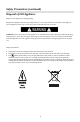
Safety Precautions Your safety and the safety of others are very important. We have provided many important safety messages in this manual for your appliance. Always read and obey all safety messages. This is the Safety Alert Symbol. This symbol alerts you to potential hazards that can cause severe bodily injury or death.
Safety Precautions (continued) For your safety, read all instructions carefully before operating the appliance. DANGER: When using an electrical appliance, basic precautions should always be followed to reduce the risk of fire, electric shock, and injury to persons. WARNING: To reduce the risk of fire, electric shock or personal injury, unplug or disconnect the appliance from the power supply before servicing.
Safety Precautions (continued) This appliance is CFC and HFC free and contains small quantities of Isobutane (R600a), an environmentally friendly coolant. You must ensure that the cooling circuit is undamaged when installing the appliance. However, if it becomes damaged, avoid proximity to open fires and heat sources of all kinds. The room in which the appliance is located should be ventilated properly and according to state and local codes. Never use an appliance with a damaged circuit.
Safety Precautions (continued) Disposal of Old Appliance Dispose of your appliance packaging properly. Refrigeration equipment must be properly disposed of in a way which protects the environment. This applies to your old appliance and to your new unit once it has reached the end of its service life. WARNING: Please ensure that old, worn appliances are rendered unusable before disposal by removing the plug, cutting the power cable, and removing or destroying any snap fastenings or bolts.
Limited Warranty Products offered through Azure Systems (“Azure”) are manufactured to provide outstanding value, and customer satisfaction is Azure’s goal for every product. As set forth below, all Azure appliances carry a twelve (12) month limited warranty on both parts and labor, and all refrigerators and freezers carry a thirty-six (36) month limited warranty on the product’s compressor. Certain exclusions to those warranties may apply.
Limited Warranty (continued) IMPROPER USE: Azure assumes no liability for component failure or other damages resulting from improper usage or installation or failure to clean and/or maintain the product as set forth in the warranty packet provided with the product. This limited warranty does not cover the cost of any inconvenience, personal injury or property damage due to improper use or product failure.
Installation Instructions Before Using Your Azure Appliance Remove all exterior and interior packing. Before connecting the appliance to the power source, let it stand upright for approximately 2 hours. This will reduce the possibility of a malfunction in the cooling system caused by handling during transportation. Clean the interior surface with warm water using a soft cloth. The door on this appliance can be opened from either the left or the right side.
Installation Instructions (continued) Built-in Cabinet Instructions These units are designed for either built-in, or free standing installation. To use this unit in a built-in application follow the dimensions listed below.
Installation Instructions (continued) Attention Never overload the cabinet. Never open the door unless necessary. Never cover shelves with aluminum foil or any other shelf material which may prevent air circulation. Should the Azure appliance be left empty for long periods, it is suggested that the appliance be unplugged, and, after careful cleaning, leave the door ajar to allow air to circulate inside the cabinet in order to avoid possible condensation, mold or odors from forming.
Installation Instructions (continued) Installing the Handle 1. Remove the door gasket on the side you wish to install the handle. Under the gasket you will see two designated holes for handle installation 2. Install the handle tightly as shown above with two screws, lock washers and flat washers provided. 3. Replace the door gasket.
How to Install and Adjust the Bottom Vent Figure 1: The legs come packaged at their lowest height of 32.5”. You can extend these legs up to 34.5” (or your desired height) by unscrewing them counterclockwise. Figure 2: Using a Philips screwdriver, remove screw #2 and bolt #3. Figure 3: Loosen the remaining two screws on the top of the door bracket and make sure there is now a gap between the door bracket and existing vent (#5).
How to Install an Overlay Panel Only for Model Numbers: A115WC-O; A124WC-O; A115BEV-O; A124BEV-O; A115R-O; A124R-O 1. Remove the door gasket from the interior of the door. 2. The screws that come with the unit are intended to be used with a ¾” front panel. 3. Clamp your front panels to the frame of the door and then anchor the panel to the door, using the screw, lock washer and flat washer provided for each mounting hole. 4. Re-install the gasket into the door assembly.
Operating Your Azure Appliance When you use your Azure appliance for the first time, or restart the appliance after having been shut off for a long period of time, there could be a few degrees variance between the temperature you select and the one indicated on the LED readout. This is normal and is due to the length of time that it was inactive. Once the appliance has been running for a few hours, the temperature readout will go back to normal.
Operating Your Azure Appliance (continued) Key Lock If in 2 minutes without touching any key, the controls will be locked automatically. To release the lock, touch the up and down marks at the same time for at least 5 seconds. Shelves • To prevent damaging the door or door gasket, make sure the door is fully open when pulling shelves out of the rail compartment. The shelves are designed with an emergency stop to prevent them being removed too far when loaded.
Care and Maintenance Cleaning Your Azure Appliance • • • • • Turn off the power, unplug the appliance, and remove all items including shelves and rack. Wash the inside surfaces with a warm water and baking soda solution. The solution should be about 2 tablespoons of baking soda to a pint of water. Wash the shelves with a mild detergent solution. Wring excess water out of the sponge or cloth when cleaning any area of the controls. Wash the outside cabinet with warm water and mild liquid detergent.
Troubleshooting Guide POSSIBLE PROBLEM Wine Center does not operate. • • • • • • • • • • • • • POSSIBLE CAUSE Not plugged in. The appliance is turned off. The circuit breaker tripped or a blown fuse. The light does not work. • • • Check the temperature control setting. External environment may require a higher setting. The door is opened too often. The door is not closed completely. The door gasket does not seal properly. The room temperature is hotter than normal.
Parts Listing A115WC-O 1 2 5 4 3 6 8 7 9 10 11 12 13 14 c F Temp. 25 23 24 22 21 20 19 18 17 16 15 Picture No. Description Part No. Picture No. Description Part No. 1 Out water tray 3.02.01.0264 14 Black door 3.02.09.1615 2 Power PCB 3.02.05.0459C 15 Small shelf 3.02.02.0818 3 Door plug 3.02.01.0216 16 Hinge fixed 3.02.02.0103B 4 Right upper hinge 3.02.02.0972A 17 Lower hinge 3.02.08.0966A 5 Display PCB 3.02.05.0463M 18 Vent 3.02.08.
Parts Listing A115WC-S 1 2 3 5 4 6 8 7 9 10 11 12 13 14 c F Temp. 25 23 24 22 21 20 19 18 17 16 15 26 Picture No. Description Part No. Picture No. Description Part No. 1 Out water tray 3.02.01.0264 14 Stainless steel door 3.02.09.1616 2 Power PCB 3.02.05.0459C 15 Small shelf 3.02.02.0818 3 Door plug 3.02.01.0216 16 Hinge fixed 3.02.02.0103B 4 Right upper hinge 3.02.02.0397C 17 Lower hinge 3.02.08.0966A 5 Display PCB 3.02.05.0463M 18 Vent 3.02.08.
Parts Listing A124WC-O 1 2 3 4 5 6 7 8 9 10 11 c F Temp. 22 21 20 19 16 18 15 14 17 13 Picture No. Description Part No. 12 Picture No. Description Part No. 3.02.09.1617 1 Compressor relays 3.02.06.0854 12 Black glass door 2 PCB Box 3.02.01.1460A 13 Door seal 3.02.01.0319 3 Power PCB 3.02.05.0459C 14 Wooden front 3.02.02.1535 4 PCB box Cover 3.02.02.0972A 15 Small wire shelf 3.02.02.0798 5 Right upper hinge 3.02.08.1820 16 Big wire shelf 3.02.02.
Parts Listing A124WC-S 1 2 3 4 5 6 7 8 9 10 11 c F Temp. 22 21 20 19 18 16 15 14 17 13 12 Picture No. Description Part No. Picture No. Description Part No. 1 Compressor relays 3.02.06.0854 12 Stainless steel door 3.02.09.1218 2 PCB Box 3.02.01.1460A 13 Door seal 3.02.01.0319 3 Power PCB 3.02.05.0459C 14 Wooden front 3.02.02.1535 4 PCB Box Cover 3.02.02.0972A 15 Small wire shelf 3.02.02.0798 5 Right upper hinge 3.02.02.0397C 16 Big wire shelf 3.02.02.
Parts Listing A115BEV-O 1 2 3 4 5 6 8 7 10 11 12 9 13 14 c F Temp. 25 24 23 22 21 20 19 18 17 16 15 26 27 Picture No. Description Part No. 28 Picture No. Description Part No. 3.02.01.2169 1 Out water tray 3.02.01.0264 15 Shelf back panel 2 Power PCB 3.02.05.0460C 16 Hinge fixed 3.02.02.0103B 3 Door plug 3.02.01.0216 17 Lower hinge 3.02.08.0966A 4 Right upper hinge 3.02.02.0972A 18 Vent 3.02.08.0822 5 Display PCB 3.02.05.0569M 19 Front foot 3.02.01.
Parts Listing A115BEV-S Picture No. Description Part No. Picture No. Description Part No. 1 Out water tray 3.02.01.0264 16 Hinge fixed 3.02.02.0103B 2 Power PCB 3.02.05.0459C 17 Lower hinge 3.02.08.0966A 3 Door plug 3.02.01.0216 18 Vent 3.02.08.0822 4 Right upper hinge 3.02.02.0397C 19 Front foot 3.02.01.0452 5 Display PCB 3.02.05.0463M 20 Back foot 3.01.01.5446 6 Temperature control sticker 3.02.03.A439 21 Heating fan 3.02.05.0181 3.02.02.0379C 3.02.08.
Parts Listing A124BEV-O 1 2 3 4 5 6 7 8 10 9 11 c F Temp. 23 22 21 20 17 19 16 18 15 14 13 Picture No. Description Part No. Picture No. 1 Compressor relays 3.02.06.0854 13 12 Description Part No. Door seal 3.02.01.0319 Small glass shelf Big glass shelf Wooden front Black wire shelf 2 PCB Box 3.02.01.1460A 14 3 Power PCB 3.02.05.0459C 15 4 PCB box Cover 3.02.02.0972A 16 5 Right upper hinge 3.02.08.1820 17 6 Light PCB 3.02.05.0465 18 Hinge fixed 3.02.02.
Parts Listing A124BEV-S 1 2 3 4 6 5 7 8 9 10 11 c F Temp. 23 22 21 20 17 19 16 18 15 14 13 12 Picture No. Description Part No. Picture No. Description Part No. 1 Compressor relays 3.02.06.0854 13 Door seal 3.02.01.0319 2 PCB Box 3.02.01.1460A 14 Small glass shelf 3.02.09.1697 3 Power PCB 3.02.05.0459C 15 Big glass shelf 3.02.09.1696 4 PCB box Cover 3.02.02.0972A 16 Wooden front 3.02.02.1535 5 Right upper hinge 3.02.08.1820 17 Black wire shelf 3.02.02.
Parts Listing A115R-O Picture No. Description Part No. Picture No. Description Part No. 1 Out water tray 3.02.01.0264 14 Black door 2.02.05.0382 2 Power PCB 3.02.05.0460C 15 Small Glass shelf 3.02.09.1658 3 Door plug 3.02.01.0216 16 Shelf back panel 3.02.01.2169 4 Right upper hinge 3.02.02.0972A 17 Hinge fixed 3.02.02.0103B 5 Display PCB 3.02.05.0569M 18 Lower hinge 3.02.08.0966A 6 Temperature control sticker 3.02.03.A439 19 Vent 3.02.08.0822 7 Light PCB 3.01.05.
Parts Listing A115R-S Picture No. Description Part No. Picture No. Description Part No. 1 Out water tray 3.02.01.0264 15 Small Glass shelf 3.02.09.1658 2 Power PCB 3.02.05.0460C 16 Shelf back panel 3.02.01.2169 3 Door plug 3.02.01.0216 17 Hinge fixed 3.02.02.0103B 4 Right upper hinge 3.02.02.0972A 18 Lower hinge 3.02.08.0966A 5 Display PCB 3.02.05.0569M 19 Vent 3.02.08.0822 6 Temperature control sticker 3.02.03.A439 20 Front foot 3.02.01.0452 7 Light PCB 3.01.05.
Parts Listing A124R-O 1 2 3 4 5 6 7 8 9 10 c F Temp. 19 18 17 16 14 15 13 12 11 Picture No. Description Part No. Picture No. Description Part No. 1 Compressor relays 3.02.06.0854 11 Black door 2.02.05.0384 2 PCB Box 3.02.01.1460A 12 Door seal 3.02.01.0319 3 Power PCB 3.02.05.0459C 13 Small glass shelf 3.02.09.1697 4 PCB box Cover 3.02.02.0972A 14 Big glass shelf 3.02.09.1696 5 Right upper hinge 3.02.08.1820 15 Hinge fixed 3.02.02.1849A 6 Light PCB 3.
Parts Listing A124R-S 1 2 3 4 5 6 7 8 9 10 11 c F Temp. 20 19 18 15 17 16 14 13 12 Picture No. Description Part No. Picture No. Description Part No. 1 Compressor relays 3.02.06.0854 11 Stainless steel handle 3.02.02.0273A 2 PCB Box 3.02.01.1460A 12 Stainless steel door 2.02.05.0380 3 Power PCB 3.02.05.0459C 13 Door seal 3.02.01.0319 4 PCB box Cover 3.02.02.0972A 14 Small glass shelf 3.02.09.1697 5 Right upper hinge 3.02.08.1820 15 Big glass shelf 3.02.