WirelessHD RX Module User’s Manual
0G Module FCC Statement : Federal Communication Commission Interference Statement This equipment has been tested and found to comply with the limits for a Class B digital device, pursuant to Part 15 of the FCC Rules. These limits are designed to provide reasonable protection against harmful interference in a residential installation.
IMPORTANT NOTE: This module is intended for OEM integrator. The OEM integrator is responsible for the compliance to all the rules that apply to the product into which this certified RF module is integrated. Additional testing and certification may be necessary when multiple modules are used. USERS MANUAL OF THE END PRODUCT: In the users manual of the end product, the end user has to be informed to keep at least 20cm separation with the antenna while this end product is installed and operated.
60G Module IC Statement : CAN ICES-3 (B)/NMB-3(B) This device complies with Industry Canada license-exempt RSS standard(s). Operation is subject to the following two conditions: (1) this device may not cause interference, and (2) this device must accept any interference, including interference that may cause undesired operation of the device. Le présent appareil est conforme aux CNR d'Industrie Canada applicables aux appareils radio exempts de licence.
USERS MANUAL OF THE END PRODUCT: In the users manual of the end product, the end user has to be informed to keep at least 20cm separation with the antenna while this end product is installed and operated. The end user has to be informed that the IC radio-frequency exposure guidelines for an uncontrolled environment can be satisfied. The end user has to also be informed that any changes or modifications not expressly approved by the manufacturer could void the user's authority to operate this equipment.
0G Module CE Statement : This equipment complies with EU radiation exposure limits set forth for an uncontrolled environment. This equipment should be installed and operated with minimum distance 20cm between the radiator & your body.
Index 1 Introduction ...................................................................................................................... 1 1.1 Product Layout ........................................................................................................ 2 1.2 Features ..................................................................................................................... 3 1.3 Package Content ..........................................................................................
1 Introduction AzureWave AW-WH064 WirelessHD RX and TX RF modules are able to transmit and receive uncompressed HDMI video, multi-channel audio and control data wirelessly by 60 GHz frequency band with 4Gbps bandwidth. AW-WH064 replaces the HDMI cable and simplifies home theater system installation. The source devices, such as BD player, Set Top Box or Tablet, they don’t need to be located near to the TV.
1.
1.2 Features Standard: WirelessHD 1.1 Frequency: 60GHz Data Rate: 4Gbps Distance: 10m (In Room) No Video Compression Latency: <1ms Support for video resolutions from 480i/576i to 1080p/60Hz ~ 8 Channels Audio (32 ~ 192KHz) Array Antenna HDMI 1.4a Compatible HDCP 2.0 Support, 128-bit AES 1.3 Package Content The package include the below package content: One set of AW-WH064T and AW-WH064R Power Adapter User’s Manual 1.
Current Max: 807mA, Average: 422mA, Min: 226mA Display Resolution Up to 1080p @60 Video Format 4:4:4 36bit Deep Color Audio Channel 2~8 Sample Rate 32-192kHz Back-channel HDMI-ARC/LR-Audio RF Specifications Frequency Range Modulation Occupied Bandwidth Output Power Receive Sensitivity 59.40~63.72GHz HRP: OFDM with QPSK , 16-QAM LRP: OFDM with BPSK HRP:1.76Ghz LRP: 92Mhz Min. Typ. Max. HRP 23 dBm 26 dBm 28 dBm LRP 18 dBm 21 dBm 31 dBm HRP: -69 dBm HRP: Up to 3.
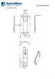
2.06 Watts Idle mode AW-WH064R Power Consumption HRP 1080p 2.26 Watts HRP 720p 2.025 Watts LRP 1.75 Watts Idle mode 1.76 Watts 2 Installation Steps 1. Connect AW-WH064T and AW-WH064R to I/O board PCBA Front view: Front view with housing: Link LED Power LED PCBA Back view: Back view with housing: TX- RX- HDMI IN Power slide switch +5V Power by MircoUSB HDMI OUT Reset button Power slide switch +5V Power by MircoUSB Reset button 2.
3 LED and Reset button behavior Power LED: It is always on after power on. Link LED behavior: LED is OFF. The module is not powered, has not yet started, or is in Power Save mode if power LED is on. LED is blinking slowly. The module has started but has not yet associated with any network. LED is blinking fast. The module is attached to a network but is disconnected (or not yet connected), meaning no video connections are currently processed. LED is ON.