
Data Sheet

24
FORM NO.: FR2-015_ A Responsible Department:WBU Expiry Date: Forever
The information contained herein is the exclusive property of AzureWave and shall not be distributed, reproduced, or disclosed
in whole or in part without prior written permission of AzureWave.
3.4.3 Frequency Reference
An external crystal is used for generating all radio frequencies and normal operation clocking. As an
alternative, an external frequency reference driven by a temperature-compensated crystal oscillator
(TCXO) signal may be used. No software settings are required to differentiate between the two. In
addition, a low-power oscillator (LPO) is provided for lower power mode timing.
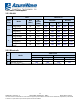
External 32.768KHz Low-Power Oscillator
Symbol
Parameter
Min
Typ
Max
Units
CLK
Clock frequency range/ accuracy
CMOS input clock signal type
±250 ppm (initial, aging,
temperature)
-
32.768
-
kHz
V
IH
Input levels, where VDDIO=1.8, 3.3V
for VIH, VIL
0.7*VDDIO
-
VDDIO_0.4
V
V
IL
-0.4
-
0.3*VDDIO
V
PN
Phase noise requirement (@
100KHz)
-
-125
-
dBc/Hz
J
C
Cycle jitter
-
1.5
-
ns
(RMS)
SR
Slew rate limit (10-90%)
-
-
100
ns
DC
Duty cycle tolerance
20
-
80
%
The AW-CM358SM module crystal specifications
Parameter
Condition
Typical
Units
Fundamental Frequencies
-
26/ 38.4
MHz
Frequency tolerance
Over operating temperature
<±10
ppm
Over process at 25℃
<±10
ppm
SMD and AT cut height
-
<1.2
Mm
Load Capacitance
-
5
pF
Maximum series resistance
-
45
Ω
Resonance mode
-
A1, Fundamental
-