AW-NM512 IEEE 802.11 b/g/n Wireless LAN And Bluetooth Module Datasheet Rev. B DF (For Standard) 1 FORM NO.: FR2-015_ A Responsible Department:WBU Expiry Date: Forever The information contained herein is the exclusive property of AzureWave and shall not be distributed, reproduced, or disclosed in whole or in part without prior written permission of AzureWave.
Features Overview Bluetooth Integrates Cypress solutions of CYW43439_A1 WiFi /BT/SoC SDIO v2.0 interfaces support for WLAN High speed UART and PCM for Bluetooth Lead-free Design 12.0mm(L) x 12.0mm(W) x 1.
Revision History Document NO: R2-2512-DST-01 Revision Version DCN NO. Date Description A 2020/09/23 DCN018490 B 2021/01/20 DCN020585 First Initial Update Specifications Table Initials Approved QM.TAN N.C Chen QM.TAN N.C Chen 3 FORM NO.: FR2-015_ A Responsible Department:WBU Expiry Date: Forever The information contained herein is the exclusive property of AzureWave and shall not be distributed, reproduced, or disclosed in whole or in part without prior written permission of AzureWave.
Table of Contents Revision History .............................................................................................................................. 3 Table of Contents ............................................................................................................................ 4 1. Introduction ................................................................................................................................. 5 1.1 Product Overview ..................................
1. Introduction 1.1 Product Overview AzureWave Technologies, Inc. introduces the advanced IEEE 802.11 b/g/n WLAN and Bluetooth combo module - AW-NM512. The module is targeted to mobile and embedded devices which need small footprint package, low power consumption, and multiple OS support. The module supports 2.4GHz IEEE 802.11n MAC/baseband/radio, and Bluetooth 5.0 compliance.
1.2 Specifications Table 1.2.1 General Features Product Description Description IEEE 802.11 b/g/n Wireless LAN and Bluetooth Module Major Chipset Cypress CYW43439 (WLBGA 63b) Host Interface WiFi + BT SDIO + UART Dimension 12.0mm(L) x 12.0mm(W) x 1.5 mm(H) Form factor Antenna Weight LGA module, 47 pins For LGA, “1T1R, external” ANT1(Main):WiFi/Bluetooth TX/RX 0.4g 1.2.2 WLAN Features WLAN Standard Description IEEE 802.
Output Power (Board Level Limit)* Receiver Sensitivity USA and Canada – 1 ~ 11 Most European Countries – 1 ~ 13 2.4G Min 11b (11Mbps) 16 @EVM<35% 11g (54Mbps) 14 @EVM≦-25 dB 11n (HT20 MCS7) 13 @EVM≦-27 dB 2.4G Min 11b (11Mbps) Typ Max Unit 18 20 dBm 16 18 dBm 15 17 dBm Typ -89 Max -84 Unit dBm 11g (54Mbps) -76 -71 dBm 11n (HT20 MCS7) -73 -68 dBm 802.11b: 1, 2, 5.5, 11Mbps 802.11g: 6, 9, 12, 18, 24, 36, 48, 54Mbps 802.
1.2.3 Bluetooth Features Bluetooth Standard Description Bluetooth 5.0 Bluetooth VID/PID N/A Frequency Range 2400~2483.5MHz Modulation GFSK (1Mbps), Π/4DQPSK (2Mbps) and 8DPSK (3Mbps) 6≤ Output Power ≤ +10 dBm (Conductive) Min Typ Output Power Receiver Sensitivity Max Unit BDR 6 8 10 dBm EDR 6 8 10 dBm Low Energy 6 8 10 dBm Min Typ -91 -91 -83 Max -86 -86 -79 Unit dBm dBm dBm DH5 2DH5 3DH5 1.2.
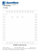
2. Pin Definition 2.1 Pin Map AW-NM512 Pin Map (Top View) 9 FORM NO.: FR2-015_ A Responsible Department:WBU Expiry Date: Forever The information contained herein is the exclusive property of AzureWave and shall not be distributed, reproduced, or disclosed in whole or in part without prior written permission of AzureWave.
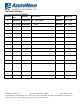
2.2 Pin Table Pin No Definition Basic Description Voltage Type VDDIO VDDIO GND RF GND Floating Floating I O VDDIO O VBAT PWR Floating Floating VDDIO I VDDIO O 1 2 3 4 5 6 7 GND WL_BT_ANT GND NC NC BT_WAKE_DEV BT_HOST_WAKE 8 CLK_REQ 9 10 11 VBAT NC NC 12 WL_REG_ON 13 WL_HOST_WAKE Ground. WLAN/BT RF TX/RX path. Ground. Floating Pin, No connect to anything. Floating Pin, No connect to anything.
25 PCM_OUT PCM data Out VDDIO O 26 PCM_CLK PCM Clock VDDIO I/O 27 PCM_IN PCM data Input VDDIO I 28 PCM_SYNC PCM Synchronization control VDDIO O 29 NC Floating Pin, No connect to anything. Floating 30 NC Floating Pin, No connect to anything. Floating 31 GND Ground. 32 NC Floating Pin, No connect to anything. 33 GND 34 BT_REG_ON 35 NC Ground. Used by PMU to power up or power down the internal regulators used by the Bluetooth section.
3. Electrical Characteristics 3.1 Absolute Maximum Ratings Symbol VBAT VDDIO Parameter Minimum Typical Maximum Unit Power supply for Internal Regulators -0.5 6 V DC supply voltage for digital I/O -0.5 3.9 V 3.2 Recommended Operating Conditions Symbol VBAT Parameter Minimum Typical Maximum Power supply for Internal Regulators 3* 3.6 Unit 4.8* V Maximum Unit *Optimal RF performance is guaranteed only for 3.2V
VOL Output Low Voltage @ 2mA - - 0.45 V Other Digital Interface VDDIO=3.3V VIH Input high voltage 2.00 - - V VIL Input low voltage - - 0.80 V VOH Output High Voltage @ 2mA VDDIO – 0.4 - - V V Output Low Voltage @ 2mA - - 0.40 V 13 FORM NO.
3.4 Host Interface 3.4.
Output delay time – Data Transfer tODLY mode Output delay time – Identification tODLY mode SDIO Bus Timing Parameters (Default Mode) 0 – 14 ns 0 – 50 ns Minimum Typical * min(VIH) = 0.7 × VDDIO and max(VIL) = 0.
Outputs: CMD, DAT (referenced to CLK) Output delay time – Data Transfer Mode tODLY – – 14 ns Output hold time tOH 2.5 – – ns Total system capacitance (each line) CL – – 40 pF SDIO Bus Timing a Parameters (High-Speed Mode) * min(Vih) = 0.7 × VDDIO and max(Vil) = 0.2 × VDDIO 3.4.2 UART Interface The AW-NM512 includes a single UART for Bluetooth. The UART is a standard 4-wire interface (RX, TX, RTS, and CTS) with adjustable baud rates from 9600 bps to 4.0 Mbps.
devices is within ±2%. UART Interface Signals PIN No. Name 40 UART_TXD 41 UART_RXD 43 UART_RTS_N 42 UART_CTS_N Description Type Bluetooth UART Serial Output. Serial data output for the HCI UART Interface Bluetooth UART Series Input. Serial data input for the HCI UART Interface Bluetooth UART Request-to-Send. Active-low request-tosend signal for the HCI UART interface Bluetooth UART Clear-to-Send. Active-low clear-to-send signal for the HCI UART interface.
3.4.3 PCM Interface Timing PCM Timing Diagram(Short Frame Sync, Master Mode) Reference Characteristics Minimum Typical Maximum Unit 12 MHz 1 PCM bit clock frequency 2 PCM bit clock low 41 3 4 5 PCM bit clock high PCM_SYNC delay PCM_OUT delay 41 0 0 6 PCM_IN setup 8 ns 7 PCM_IN hold Delay from rising edge of PCM_BCLK during last bit period to PCM_OUT becoming high impedance 8 ns 8 0 ns 25 25 25 ns ns ns ns 18 FORM NO.
PCM Timing Diagram(Short Frame Sync, Slave Mode) Reference Characteristics Minimum Typical Maximum Unit 12 MHz 1 PCM bit clock frequency 2 PCM bit clock low 41 ns 3 4 5 PCM bit clock high PCM_SYNC setup PCM_SYNC hold 41 8 8 ns ns ns 6 PCM_OUT delay 0 7 8 PCM_IN setup PCM_IN hold Delay from rising edge of PCM_BCLK during last bit period to PCM_OUT becoming high impedance 8 8 9 0 25 ns ns ns 25 ns 19 FORM NO.
PCM Timing Diagram(Long Frame Sync, Master Mode) Reference Characteristics Minimum Typical Maximum Unit 12 MHz 1 PCM bit clock frequency 2 PCM bit clock low 41 ns 3 4 5 PCM bit clock high PCM_SYNC delay PCM_OUT delay 41 0 0 ns ns ns 6 PCM_IN setup 8 ns 7 PCM_IN hold Delay from rising edge of PCM_BCLK during last bit period to PCM_OUT becoming high impedance 8 ns 8 0 25 25 25 ns 20 FORM NO.
PCM Timing Diagram(Long Frame Sync, Slave Mode) Reference Characteristics Minimum Typical Maximum Unit 12 MHz 1 PCM bit clock frequency 2 PCM bit clock low 41 ns 3 4 5 PCM bit clock high PCM_SYNC setup PCM_SYNC hold 41 8 8 ns ns ns 6 PCM_OUT delay 0 7 8 PCM_IN setup PCM_IN hold Delay from rising edge of PCM_BCLK during last bit period to PCM_OUT becoming high impedance 8 8 9 0 25 ns ns ns 25 ns 3.
WLAN = ON, Bluetooth = OFF WLAN = OFF, Bluetooth = ON 22 FORM NO.: FR2-015_ A Responsible Department:WBU Expiry Date: Forever The information contained herein is the exclusive property of AzureWave and shall not be distributed, reproduced, or disclosed in whole or in part without prior written permission of AzureWave.
3.6 Frequency References The AW-NM512 uses an external 26MHz xtal for normal operation and an external secondary low frequency clock for low-power-mode timing. Either the internal low-precision LPO or an external 32.768 kHz precision oscillator is required. The internal LPO frequency range is approximately 33 kHz ± 30% over process, voltage, and temperature, which is adequate for some applications.
Parameter LPO Units Nominal input frequency Frequency accuracy Duty cycle Input signal amplitude 32.768 +-200 30 - 70 200 - 3300 >100 <5 Square-wave or sine-wave <10000 kHz ppm % mV , p-p kΩ pF ppm Input impedance Signal type Clock jitter (during initial start-up) 3.7 Power Consumption* 3.7.1 WLAN Band (GHz) 2.4 (5)(6) Mode 11b@1Mbps 11b@11Mbps 11g@6Mbps 11g@54Mbps 11n@MCS0 11n@MCS7 Transmit Receive BW (MHz) RF Power (dBm) Max. Avg. Duty. (%) Max. Avg.
Federal Communication Commission Interference Statement This device complies with Part 15 of the FCC Rules. Operation is subject to the following two conditions: (1) This device may not cause harmful interference, and (2) this device must accept any interference received, including interference that may cause undesired operation. This equipment has been tested and found to comply with the limits for a Class B digital device, pursuant to Part 15 of the FCC Rules.
Radiation Exposure Statement: This equipment complies with FCC radiation exposure limits set forth for an uncontrolled environment. This equipment should be installed and operated with minimum distance 20cm between the radiator & your body. This module is intended for OEM integrators only. Per FCC KDB 996369 D03 OEM Manual v01 guidance, the following conditions must be strictly followed when using this certified module: KDB 996369 D03 OEM Manual v01 rule sections: 2.
RF I/O interface to antenna connector on the PCB shall accomplished via microstrip MHF4 connector. The multiplexer on carry board PCB with interface to antenna. The connector on carry board PCB with interfaces to antenna must be of a unique type to disable connection to a non-permissible antenna in compliance with FCC section 15.203. The following connectors are allowed.
2.6 RF exposure considerations This equipment complies with FCC mobile radiation exposure limits set forth for an uncontrolled environment. This equipment should be installed and operated with a minimum distance of 20cm between the radiator & your body. If the module is installed in a portable host, a separate SAR evaluation is required to confirm compliance with relevant FCC portable RF exposure rules. 2.
IMPORTANT NOTE: In the event that these conditions can not be met (for example certain laptop configurations or co-location with another transmitter), then the FCC authorization is no longer considered valid and the FCC ID can not be used on the final product. In these circumstances, the OEM integrator will be responsible for re-evaluating the end product (including the transmitter) and obtaining a separate FCC authorization.
L’exploitation est autorisée aux deux conditions suivantes : (1) le dispositif ne doit pas produire de brouillage préjudiciable, et (2) ce dispositif doit accepter tout brouillage reçu, y compris un brouillage susceptible de provoquer un fonctionnement indésirable. Radiation Exposure Statement: This equipment complies with ISED radiation exposure limits set forth for an uncontrolled environment. This equipment should be installed and operated with greater than 20cm between the radiator & your body.
In the event that these conditions can not be met (for example certain laptop configurations or co-location with another transmitter), then the Canada authorization is no longer considered valid and the IC ID can not be used on the final product. In these circumstances, the OEM integrator will be responsible for re-evaluating the end product (including the transmitter) and obtaining a separate Canada authorization.
L'intégrateur OEM doit être conscient de ne pas fournir des informations à l'utilisateur final quant à la façon d'installer ou de supprimer ce module RF dans le manuel de l'utilisateur du produit final qui intègre ce module. Le manuel de l'utilisateur final doit inclure toutes les informations réglementaires requises et avertissements comme indiqué dans ce manuel.