
Data Sheet


27
FORM NO.: FR2-015_ A Responsible Department:WBU Expiry Date: Forever
The information contained herein is the exclusive property of AzureWave and shall not be distributed, reproduced, or
disclosed in whole or in part without prior written permission of AzureWave.
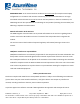
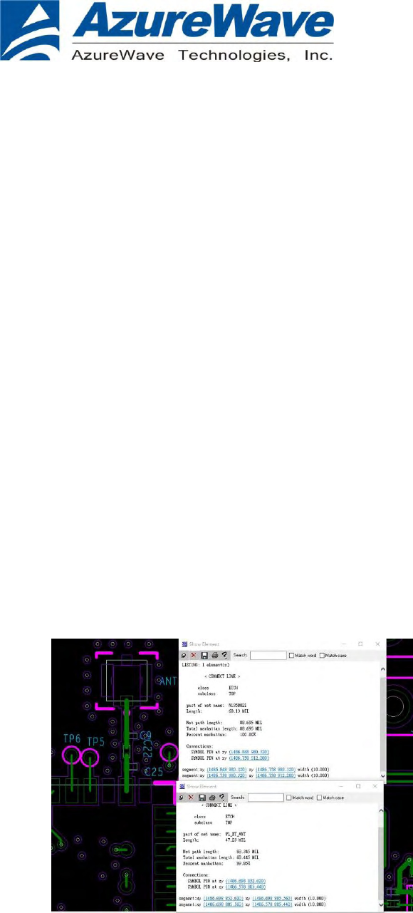
RF I/O interface to antenna connector on the PCB shall accomplished via microstrip MHF4 connector.
The multiplexer on carry board PCB with interface to antenna. The connector on carry board PCB with
interfaces to antenna must be of a unique type to disable connection to a non-permissible antenna in
compliance with FCC section 15.203. The following connectors are allowed.
MHF4 Connector: I-PEX, model 20449-001E or equivalent Custom 50 ohm coaxial pigtail from PCB to
antenna
AW-NM512 shall follow the above design rule for characteristic impedance of 50 ohms +/- 10% and
measure microstrip or stripline transmission line width on PCB.
Any deviation(s) from the defined parameters described above require that the host product
manufacturer notify the module grantee that they wish to change the antenna trace design. In this case,
a Class II permissive change application is required to be filed by the grantee, or the host manufacturer
can take responsibility through the change in FCC ID (new application) procedure followed by a Class II
permissive change application.