
Installation manual

SMA America, LLC 4 Product Description
Installation Manual SB30-40-US-IA-en-34 23
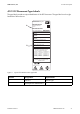
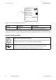
4.3 DC Disconnect
The DC Disconnect safely disconnects the PV array from the inverter.
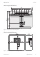
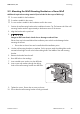
Figure 7: DC Disconnect design
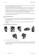
The DC Disconnect connects the PV array to the inverter. Turning the rotary switch interrupts the flow
of current and the DC cabling can be safely disconnected from the inverter.
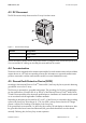
4.4 Communication
The inverter can be equipped with a communication module for wired communication with special data
capture devices or a PC with corresponding software (for information on supported communication
products connected to with the communication module, see www.SMA-America.com).
4.5 Ground-Fault Protective Device (GFDI)
According to the National Electrical Code
®
, Section 690.5, the Sunny Boy has a system for detecting
ground-fault errors in the PV array.
The PV array is operated in a grounded configuration. The grounding of a PV plant is established as
per the specifications of Section 690.41 to 690.47 of the National Electrical Code
®
ANSI/NFPA
70 and is the responsibility of the electrically qualified person. Installations in Canada must be carried
out in accordance with the applicable Canadian standards.
Depending on the plant type, the cable for DC+ or DC − of the PV array is connected to the grounding
system in the Sunny Boy. According to UL 1741, the GFDI is always active when the DC voltage
present is sufficient for switching on the display in the Sunny Boy.
If the ground-fault current exceeds 1 A, the Sunny Boy switches off and displays a disturbance. After
the ground-fault has been located and eliminated, the ground-fault disturbance must be cleared
manually. Following this, the Sunny Boy resumes operation.
Position Designation
ARotary Switch
BCover