
Installation manual

SMA America, LLC 6 Electrical Connection
Installation Manual SB30-40-US-IA-en-34 47
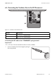
1. Ensure that the inverter is grounded as prescribed (see Section 6.4.3 "Grounding the DC
Input", page 44).
2. Ensure that the DC Disconnect is grounded as prescribed (see Section 6.4.2 "Grounding the
DC Disconnect", page 43).
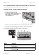
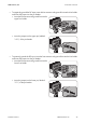
3. To connect the PV array with negative polarity to the DC Disconnect, connect the DC cables:
• Connect the DC+ cables to the "UNGROUNDED" screw terminal (torque: 15 in-lb. (1.7 Nm)).
• Connect the DC − cables to the "GROUNDED" screw terminal (torque: 15 in-lb. (1.7 Nm)).
4. To connect the PV array with positive polarity to the DC Disconnect, connect the DC cables:
• Connect the DC − cables to "UNGROUNDED" screw terminal (torque: 15 in-lb. (1.7 Nm)).
• Connect the DC+ cables to "GROUNDED" screw terminal (torque: 15 in-lb. (1.7 Nm)).
5. Ensure that all screw terminals are correctly connected and that the cables are securely
positioned in the screw terminals.
6.4.5 Connecting the DC Cable of the DC Disconnect to the Inverter
The PV array must be connected to the inverter via the DC Disconnect, taking into account the
necessary type of grounding.
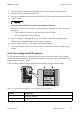
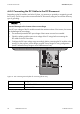
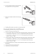
Inserting the DC cable of the DC Disconnect into the inverter
1. Open the inverter (see Section 9.1).
2. In order to connect the DC cable of the DC
Disconnect, pierce a hole in the center of the rubber
grommet in the enclosure opening.
Use a screwdriver for this.
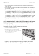
3. Insert the DC cable of the DC Disconnect into the inverter through the rubber grommet.
4. Pull back the DC cable of the DC Disconnect slightly. This seals the rubber grommet.