
Installation manual

6 Electrical Connection SMA America, LLC
48 SB30-40-US-IA-en-34 Installation Manual
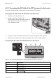
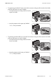
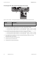
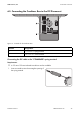
Connecting the DC cable of the DC disconnect to the inverter
Figure 20: DC+ and DC − connecting terminal plates for connecting the DC cable of the DC Disconnect
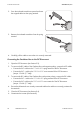
To connect the PV array with negative polarity to the inverter, connect the DC cables:
• Connect the black insulated conductor to screw terminal DC+ (torque: 15 in-lb. (1.7 Nm)).
• Connect the white insulated conductor to screw terminal DC − (torque: 15 in-lb. (1.7 Nm)).
To connect the PV array with positive polarity to the inverter, connect the DC cables:
• Connect the white insulated conductor to screw terminal DC+ (torque: 15 in-lb. (1.7 Nm)).
• Connect the black insulated conductor to screw terminal DC − (torque: 15 in-lb. (1.7 Nm)).
5. Ensure that all screw terminals are correctly connected and that the cables are securely
positioned in the screw terminals.
6. Close the DC Disconnect (see Section 9.4).
7. Close the inverter (see Section 9.2).
8. Commission the inverter (see Section 8).
Position Designation
A Screw terminal DC+
B Screw terminal DC −