
Installation manual


SMA America, LLC 10 Troubleshooting
Installation Manual SB30-40-US-IA-en-34 65
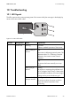
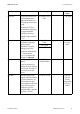
10.2 Measurement Channels
In the measurement channels, the measured values of the inverter are shown on the display. In
addition, you can read out a series of measurement channels and messages of the inverter via special
communication devices (e.g. Sunny WebBox) or a PC with corresponding software
(e.g. Sunny Explorer).
Glows for 5 s,
goes out for 3 s,
blinks 4 times
High DC input voltage
The inverter has detected a DC input voltage
that is too high for safe operation.
Glows for 5 s,
goes out for 3 s,
blinks 5 times
Disturbance
The inverter has detected an internal fault that
interrupts normal operation:
B + C Red LED +
yellow LED
Glowing ground-fault
The inverter has detected a ground-fault. The
inverter will not restart automatically after
detecting a ground-fault.
Corrective measures:
• Check the PV plant for ground-faults
(see Section 11.6).
A + B + C All LEDs Glowing Initialization
The inverter is initializing. The DC current
available from the PV array is not sufficient for
normal operation. Data transmission is not
possible during initialization.
A + B + C All LEDs Not glowing Standby
The inverter is in standby mode. The DC input
voltage is too low for operation.
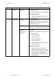
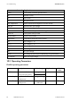
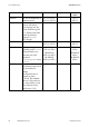
Measurement channel Explanation
CO2 saved Amount of CO2 saved during operation time
E-total Total energy yield
Error Description of an error
Event-Cnt Number of events
Fac Power frequency
Grid type Type of power distribution grid to which the inverter is connected
h-on Total operating hours
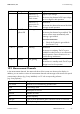
Position Designation Status Explanation