00-POE4 Unmanaged Industrial 4-Port Mid-Span POE PSE User Manual & Installation Guide (Revised 8/5/2009) 1
Industrial 4-Port Mid-Span POE PSE Installation Guide 100-POE4 (Revised 8/5/2009) 2
Copyright, © N-TRON Corp., 2008 820 S. University Blvd., Suite 4E Mobile, AL USA 36609 All rights reserved. Reproduction, adaptation, or translation without prior written permission from N-TRON Corp. is prohibited, except as allowed under copyright laws. Ethernet is a registered trademark of Xerox Corporation. All other product names, company names, logos or other designations mentioned herein are trademarks of their respective owners.
GENERAL SAFETY WARNINGS WARNING: Do not operate the equipment in the presence of flammable gasses or fumes. Operating electrical equipment in such an environment constitutes a definite safety hazard. WARNING: If the equipment is used in the manner not specified by N-TRON Corp., the protection provided by the equipment may be impaired. WARNING: Do not perform any services on the unit unless qualified to do so. Do not substitute unauthorized parts or make unauthorized modifications to the unit.
HAZARDOUS LOCATION INSTALLATION REQUIREMENTS 1. This equipment is suitable for use in Class I, Div 2, Groups A, B, C, and D, or unclassified or nonhazardous locations only. 2. WARNING: Explosion Hazard - Substitution of components may impair suitability for Class I, Division 2. 3. WARNING: Explosion hazard, do not disconnect while the circuit is live or unless the area is known to be non-hazardous. 4.
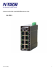
Functional Overview The 100-POE4 industrial 4-port Mid-Span POE PSE is designed to provide power over Ethernet for POE capable devices where running a power line is either not possible or not cost effective. This feature allows an end user to power a POE camera, wireless access point, or any other POE capable device without the need for running separate wires for power. This also allows the ability for a centralized battery backup for all these devices.
PACKAGE CONTENTS Please make sure the package contains the following items: 1. 2. 100-POE4 Instruction Sheet Contact your carrier if any items are damaged. UNPACKING Remove all the equipment from the packaging, and store the packaging in a safe place. File any damage claims with the carrier. CLEANING Clean only with a damp cloth.
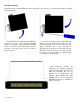
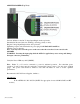
DIN-Rail Mounting Install the unit in a standard DIN rail. Recess the unit to allow at least 2” of horizontal clearance for CAT5e cable bend radius. To install the unit to 35mm industrial DIN rail, place the top edge of the included mounting bracket on the back of the unit against the DIN rail at a 15° angle as shown. Rotate the bottom of the unit to the back (away from you) until it snaps into place.
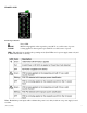
FRONT PANEL From Top to Bottom: V1 POE V2 POE Power LED POE is being applied on the respective port with V1 as a valid source of power. is being applied on the respective port with V2 as a valid source of power. LEDs: The table below describes the operating modes (Port LEDs are for power supply status only and do NOT indicate link or activity): Note: Redundant power inputs will not balance the power load. Only load from one power supply is used at a time.
APPLYING POWER (Top View) Unscrew & Remove the DC Voltage Input Plug from the top header. Install the DC Power Cables into the Plug (observing polarity on unit). Plug the Voltage Input Plug back into the top header. Tightening torque for the terminal block power plug is 0.22 Nm/0.162 Pound Foot. Turn the power on the wire. Note: It is only safe to turn the power on the wires after the wires have been secured to the 100-POE4.
N-TRON 100-POE4 MID-SPAN POE GROUNDING TECHNIQUES The grounding philosophy of any control system is an integral part of the design. N-Tron switches are designed to be grounded, but the user has been given the flexibility to float the switch when required. The best noise immunity and emissions (i.e. CE) are obtained when the N-Tron switch chassis is connected to earth ground via a drain wire. Some N-Tron switches have metal din-rail brackets that can ground the switch if the din-rail is grounded.
RJ45 CONNECTOR CRIMP SPECIFICATIONS Please reference the illustration below for your Cat5 cable specifications: (Revised 8/5/2009) 12
TYPICAL APPLICATION CONNECTING THE UNIT For 10Base-T ports, plug a Category 3 (or greater) twisted pair cable into the RJ45 connector. For 100Base-T ports, plug a Category 5 (or greater) twisted pair cable into the RJ45 connector. Connect the other end to the far end station. The total length of cable should not exceed 100 meters. Although power is being applied to the Ethernet port, the power does not boost data on the lines. TROUBLESHOOTING 1. Make sure the (Power LED) is ON. 2.
FCC STATEMENT This product complies with Part 15 of the FCC-A Rules. Operation is subject to the following conditions: (1) This device may not cause harmful interference (2) This device must accept any interference received, including interference that may cause undesired operation. NOTE: This equipment has been tested and found to comply with the limits for a Class A digital device, pursuant to Part 15 of the FCC Rules.
Regulatory Approvals: Safety: UL Listed per ANSI/ISA-12.12.01-2000 (US and Canada) and is listed for use in Class I, Div 2, Groups A, B, C, D, T4A EMI: EN 61000-6-4, EN 55011 - Class A FCC Title 47, Part 15, Subpart B - Class A ICES-003 – Class A EMS: EN 61000-6-2 IEC 61000-4-2 (ESD) IEC 61000-4-3 (RS) IEC 61000-4-4 (EFT) IEC 61000-4-5 (Surge) IEC 61000-4-6 (Conducted Disturbances) Warranty: 3 years from the date of purchase.
KEY SPECIFICATIONS Physical Height: Width: Depth: Weight: DIN-Rail: Electrical Input Voltage: Steady Input Current: Steady Input Current: Inrush Current: 3.5” (8.89cm) 1.489” (3.78cm) 3.53” (8.96cm) 0.7 lbs. (0.31kg) 35mm Input Ripple: Input Wire Size: 46-49 VDC 1.6 A @ 48 VDC (under full load) 30 mA @ 48 VDC (under no load) 27 Amp/1.5 ms @ 48VDC (under full load) 24 Amp/1.
N-TRON Limited Warranty N-TRON, Corp. warrants to the end user that this hardware product will be free from defects in workmanship and materials, under normal use and service, for the applicable warranty period from the date of purchase from N-TRON or its authorized reseller.