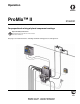
Operation ProMix™ II For proportional mixing of plural component coatings Important Safety Instructions Read all warnings and instructions in this manual. Save these instructions. See page 3 for model information, including maximum working pressure and approvals.
Contents ◆ Contents Contents . . . . . . . . . . . . . . . . . . . . . . . . . . . . . . . . . . 2 Manual Conventions . . . . . . . . . . . . . . . . . . . . . . . . 2 ProMix™ II Models . . . . . . . . . . . . . . . . . . . . . . . . . 3 Related Manuals . . . . . . . . . . . . . . . . . . . . . . . . . . . 4 Warnings . . . . . . . . . . . . . . . . . . . . . . . . . . . . . . . . . 6 Overview . . . . . . . . . . . . . . . . . . . . . . . . . . . . . . . . . . 8 Usage . . . . . . . . . . . . . . . . . . . .
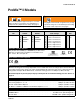
ProMix™ II Models ◆ ProMix™ II Models WARNING WARNING Do not install equipment approved only for a non-hazardous location in a hazardous area. Substitution of components may impair intrinsic safety. See page 6. Enter PM ProMix™ II Unit A Meter PM 0 1 2 3 None G3000 G3000HR Coriolis Changing the fluid manifold configuration may change its pressure rating. Do not exceed the pressure rating of the lowest rated component. See page 6.
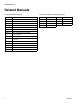
Related Manuals ◆ Related Manuals Component Manuals in English Manual Description Manual Language Manual Language 310633 310653 310654 310655 308778 310696 310656 307731 ProMix™ II Operation ProMix™ II Service - Parts Fluid Mix Manifold Dispense Valve G3000, G3000HR Flow Meter Coriolis Flow Meter Color Change Kit Color Change Valve Assembly, Low Pressure Color Change Valve, Low Pressure Color Change Valve Assembly, High Pressure Color Change Valve, High Pressure Gun Flush Box Printer ProMix™ II Dat
Related Manuals ◆ 310633C 5
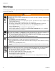
Warnings ◆ Warnings The following warnings include general safety information for this equipment. More specific warnings are included in the text where applicable. WARNING FIRE AND EXPLOSION HAZARD Flammable fumes, such as solvent and paint fumes, in work area can ignite or explode. To help prevent fire and explosion: • Use equipment only in well ventilated area. • Eliminate all ignition sources; such as pilot lights, cigarettes, portable electric lamps, and plastic drop cloths (potential static arc).
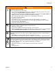
Warnings ◆ WARNING EQUIPMENT MISUSE HAZARD Misuse can cause death or serious injury. • Do not exceed the maximum working pressure or temperature rating of the lowest rated system component. See Technical Data in all equipment manuals. • Use fluids and solvents that are compatible with equipment wetted parts. See Technical Data in all equipment manuals. Read fluid and solvent manufacturer’s warnings. • Check equipment daily. Repair or replace worn or damaged parts immediately.
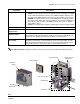
Overview ◆ Usage Overview Usage The Graco ProMix™ II is an electronic two-component paint proportioner. It can blend most two-component solvent and waterborne epoxy, polyurethane, and acid-catalyzed paints. It is not for use with “quick-setting” paints (those with a potlife of less than 15 minutes). • • • Can proportion at ratios from 0.1:1–30:1 in 0.1 increments. Has user selectable ratio assurance and can maintain up to +/-1% accuracy, depending on materials and operating conditions.
Overview ◆ Component Identification and Definition Component Description Flow Meters Three optional flow meters are available from Graco: • G3000 is a general purpose gear meter typically used in flow ranges of 75-3000 cc/min. (0.02–0.79 gal/min.), pressures up to 4000 psi (28 MPa, 276 bar), and viscosities of 20–3000 centipoise. The K-factor is approximately 0.119 cc/pulse. • G3000HR is a high resolution version of the G3000 meter. It is typically used in flow ranges of 38–1500 cc/min. (0.01–0.
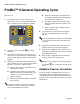
ProMix™ II General Operating Cycle ◆ ProMix™ II General Operating Cycle d. Dispense Valve B opens, and fluid flows into Refer to FIG. 2 the integrator chamber (K) and is aligned proportionately with component A. 1. The spray gun operator enters and loads the desired color. The color change LED blinks while color is loading, then turns solid when complete. LED Color e. Flow Meter B (G) monitors the fluid volume dispensed and sends electrical pulses to the controller. f.
ProMix™ II General Operating Cycle ◆ Air Flow Switch Function Key: A B C D E F G H J K L M L J Dispense Valve A Dispense Valve B Flow Meter A Component A Supply Line Air Purge Valve Shutoff Valve A Flow Meter B Component B Supply Line Solvent Purge Valve Integrator Static Mixer Fluid Supply to Gun K F H E G D B C A M FIG.
Installation ◆ Typical Installation Installation • Reference numbers and letters in parentheses in the text refer to numbers and letters in the illustrations. • Icons in the text refer to icons on the equipment or keypad. • FIG. 4 and FIG. 5, page 14, show typical installations. Contact your Graco distributor for actual system designs. • Be sure all accessories are adequately sized and pressure-rated to meet system requirements.
Installation ◆ Typical Installation G F D H G H C E L M N S K T J H P A S Q R T B TI4658A FIG.
Installation ◆ Installation Requirements Installation Requirements NON-HAZARDOUS LOCATION ONLY Safety Barrier ProMix™ II EasyKey Interface Power and Communication Cable Power Cable ProMix™ II Smart Fluid Panel Fiber Optic Communication Cable Operator Station 234441 Pneumatic Interface Gun Flush Box 234443 250 VAC Maximum Supply Voltage Flow Meter Flow Meter HAZARDOUS (CLASSIFIED) LOCATION FIG.
Installation ◆ Location Requirements Location Requirements WARNING Smart Fluid Panel: Install according to requirements for : Non-intrinsically Safe Installation (FIG. 4) or Intrinsically Safe Installation (FIG. 5) and at a convenient location to connect to paint and solvent supplies. For an Intrinsically Safe Installation, the Smart Fluid Panel may be located inside or outside the hazardous location. Install according to appropriate electrical codes.
Installation ◆ Mounting Mounting Dimensions 1. Follow Location Requirements, page 15. 2. Ensure that the wall and mounting hardware are EasyKey™ Display strong enough to support the weight of the equipment (see Technical Data, page 56), fluid, hoses, and stress caused during operation. .3 in. (7.6 mm) 12 in. (304.8 mm) 3. Using the equipment as a template, mark the mounting holes on the wall at a convenient height for the operator and so equipment is easily accessible for maintenance. FIG. 7. 4.
Installation ◆ Air Supply Connections Air Supply Connections Required • Compressed air supply pressure: 75-100 psi (517-700 kPa, 5.2-7 bar). • Air hoses: use grounded hoses that are correctly sized for your system. Use separate air supply lines for the following two connections (X and L) to avoid contaminating the purge air line (X) with fluid if the air purge valve and a check valve failed. 3. Connect a clean air supply line to the shutoff valve WARNING (L).
Installation ◆ Air Supply Connections CAUTION The ProMix™ II potlife timer will not function properly when used with multiple guns operating simultaneously. To avoid having mixed material set in the equipment, carefully monitor potlife by some other means. 6. For air spray, HVLP, and air-assist airless gun applications: • • N Systems without a Gun Flush Box, connect the gun air supply line between the Smart Fluid Panel gun air outlet (N - FIG. 9) and the spray gun air inlet (AA - FIG. 10).
Installation ◆ Fluid Supply Connections Fluid Supply Connections 3. Connect the component B line to the component B flow meter inlet (DD). FIG. 12. WARNING Do not exceed the pressure rating of the lowest rated component. Refer to the product ID Label. Read ProMix™ II Models information, page 3. The component A and B fluid meter inlets (R, DD) have fluid check valves to prevent backflow from fluid supply pressure fluctuations. Backflow can cause ratio inaccuracies. 4.
Installation ◆ Cable Connections Cable Connections • All electrical wiring must be done by a qualified electrician and comply with all local codes and regulations. • Enclose all cables routed in the spray booth and high traffic areas in conduit to prevent damage from paint, solvent, and traffic. • All options ordered on the ProMix™ II system are electrically tested at the factory. A C V Power Requirements FIG.
Installation ◆ Cable Connections 4. Route the opposite Fiber Optic Cable end through the Smart Fluid Panel strain relief connector (D). FIG. 15. Do not route the cable with tight bends or kinks. The fiber optic cable has a minimum bend radius of 1.6 in. (40 mm). 6. Tighten the strain relief connector Connect Operator Station to Smart Fluid Panel The Operator Station cable (F) is factory wired into the Operator Station. FIG. 17. Do not disconnect the cable except to replace it. Route the 50 ft. (15.
Installation ◆ Cable Connections Adding Flow Meters If using flow meters other than those supplied with the system: • You must provide a separate power source to the flow meter (unless it is a Graco G3000, G3000HR, or Graco HG6000 helical meter). • Route the signal cables through the Smart Fluid Panel holes (J - FIG. 19) and into the enclosure through the strain reliefs (GG - FIG. 20). Leave enough slack in the cable so the enclosure (K) can be raised for service. • See FIG.
Installation ◆ Grounding Grounding WARNING W Your system must be grounded. Read warnings, page 6. For Intrinsic Safety: Ground wires for the EasyKey™ Display, Smart Fluid Panel, Operator Station, and Gun Flush Box must all be connected to the same true earth ground. See FIG. 26, page 25. Different ground points may cause current to flow through component cables, causing incorrect signals. FIG. 22 Smart Fluid Panel Connect a ground wire from the Smart Fluid Panel ground lug (EE) to a true earth ground.
Installation ◆ Grounding Gun Flush Box Air and Fluid Hoses: Connect a ground wire from the Gun Flush Box ground lug (BB) to a true earth ground. FIG. 25. Use grounded hoses only. Spray Gun BB Follow the grounding instructions in your gun manual. Fluid Supply Container Follow local code. Object Being Sprayed Follow local code. FIG. 25 Flow Meters Connect the meter cables as instructed on page 22. Failure to properly connect the shield may cause incorrect signals.
Installation ◆ Check Resistance 4 2 5 7 8 1 10 9 3 6 Key: Ground wires for the EasyKey™ Display, Smart Fluid Panel, Operator Station, and Gun Flush Box must all be connected to the same true earth ground. See FIG. 26, page 25.
Operator Controls ◆ Operator Station Operator Controls Two devices provide operator interface; they are the Operator Station and the Keypad on the EasyKey™ Display. Operator Station Used by the operator for daily painting functions including: choosing color, initiating report printing, reading/clearing alarms, and placing the system in Standby, Mix, or Purge mode. It is typically mounted inside the booth or near the painter.
Operator Controls ◆ Operator Station Color change and alarm indicator • Normally displays color number. • If an alarm occurs, displays an alarm code, E1 to E9. • Color number displays after alarm is cleared. Color change sequence indicator (green LED) • Stays lit while a color is in use. • Shuts off when or keys are pressed. • If a new color is entered, the LED blinks while the color is loaded and turns solid after loading is complete.
Operator Controls ◆ EasyKey™ Display EasyKey™ Display LCD Display Keypad AC Power Switch Serial Printer Port (RS-232) Graco PC Cable Port Audible Alarm FIG. 28 AC Power Switch Backlit LCD Display Turns system AC power on or off. Shows graphical and text information related to setup and spray operations. There is a screen saver option available in the Advanced Setup Screen 3. Pressing any key brings the display out of screen saver mode.
Operator Controls ◆ EasyKey™ Display Printer Port Ethernet Connection The serial printer port (RS-232) is used with optional Printer Kit 234670, which enables you to print individual job tickets after each dispense transaction is complete. See page 43. Refer to printer manual 308818 for additional information. You can access data from the ProMix™ II on an office or industrial network or through the internet with the proper network configuration.
Run Mode ◆ Power Up Screens Run Mode Power Up Screens 3 Potlife Timer: shows remaining potlife time in min- When the EasyKey™ power switch is turned on, the Graco logo and current software revision displays. 4 Actual Ratio: in hundredths. utes. Run Screen 5 Current Flow Rate: in cc/min. This screen displays the operating status of the system and is the default screen after powering up. 6 Total Job Volume: in cc or oz.
Setup Mode ◆ Entering Setup Setup Mode Entering Setup Setup Screen Menu Press the Setup The Setup Screen Menu appears at the bottom of all Setup screens, with the current screen highlighted. FIG. 32. key to enter or exit Setup. Password Screen If a password was activated, you must enter the password before entering Setup mode. Refer to Advanced Screen 3, page 37. Entering the wrong password returns you to the Run Screen. Advanced setup has 3 screens. All other setup selections have only 1 screen.
Setup Mode ◆ Color Screen Color Screen Potlife Time Set the potlife time from 1–999 minutes in increments of 1 minute. Select a time that is within your material’s sprayable potlife time so if the potlife is exceeded and an alarm occurs, you have sufficient time to spray or purge the mix material from the system. Dropdown list Setup Screen Menu CAUTION The ProMix™ II potlife timer will not function properly when used with multiple guns operating simultaneously.
Setup Mode ◆ Color Screen ProMix™ II Purge Sequence Legend: Pa: Air purge valve Ps: Solvent purge valve Ps-final: Solvent purge valve (final solvent fill is 25% of purge time) 25% of Purge Time Pa Ps Pa Ps Pa Ps Pa PS-final Pa = Air chop time set in Advance Screen 1, page 35. Ps = Solvent chop time set in Advance Screen 1, page 35.
Setup Mode ◆ Report Screen Report Screen Calibrate Screen FIG. 37: Setup Mode - Calibrate Screen FIG. 36: Setup Mode - Report Screen The Report Screen shows the most recent 10 alarms, with the date and time. Use the or keys to see all the alarms. The grand total of components A and B is displayed in liters or gallons, based on the units set in Advanced Screen 1. Grand total cannot be reset. There are no selectable settings on the Report Screen. Use this screen to calibrate a meter.
Setup Mode ◆ Advanced Screens Advanced Screens Example: Material Usage Report Material Usage Start Time: 09-Dec-2003 12:24:08 End Time: 09-Dec-2003 12:26:19 Color A (cc) B (cc) 1 51 17 2 0 0 3 100 25 4 20 10 5 0 0 6 0 0 Advanced setup has 3 screens. The screen number appears on the right side of the screen. FIG. 38. Press key to show drop-down lists and to enter your selection. Advanced Screen 1 Display Units Screen Number Select cc/Liter (default) or oz/Gallon.
Setup Mode ◆ Advanced Screens Air Chop Defines time (in seconds) that air is dosed during air-solvent chop, which is used during the purge and color change sequences. Set from 0-999 seconds. Default is 1 second. Solvent Chop The potlife volume is set in either ounces or cc based on units selected in Advanced Screen 1. Set from 0-999 cc or 0-33 ounces. If you change the units, this value updates to the new units. Default is 350 cc (12 oz.).
Setup Mode ◆ Advanced Screens Gun Flush Box Advanced Screen 3 Select Off (default) or On, depending on whether you have a gun flush box. Autodump Select Off (default) or On. You can only use Autodump if you have a gun flush box. If On, ProMix™ II will automatically purge the mixed material 2 minutes after potlife time has expired, and the gun is in the gun flush box. This prevents mixed material from setting up in the material lines.
Operation ◆ Pressure Relief Procedure Operation 8. Engage trigger lock. Pressure Relief Procedure 9. Press Standby WARNING on Operator Station. 10. If you suspect that the spray tip or hose is clogged Follow Pressure Relief Procedure when you stop spraying, before changing spray tips, and before cleaning, checking, or servicing equipment. Read warnings, page 6.
Operation ◆ Start Up Start Up 1. Go through Checklist, ✓ Checklist 1B 1A System grounded Verify all grounding connections were made. See Grounding, page 23. All connections tight and correct Verify all electrical, fluid, air, and system connections are tight and installed according to Installation instructions, page 12. 4B 4A Fluid supply containers filled Check component A and B and solvent supply containers. 2B 2A 3A Mix manifold valves set Check that mix manifold valves are set correctly.
Operation ◆ Start Up 2. Turn the EasyKey™ Display AC Power Switch on (I = on, 0 = off). ➜ Graco logo and software revisions display, followed by Run screen. ➜ In bottom left corner, the system status displays, which can be Standby, Mix, Purge, or an alarm notification. Eas y K ey 3. If this is the first time starting up the system, purge it as instructed in Purging Fluid Supply System, page 46.
Operation ◆ Start Up 11. Adjust the flow rate. The fluid flow rate shown on the EasyKey™ Run screen is for either component A or B, depending on which dispense valve is open. The fluid supply lines on the screen highlight to show which dispense valve is open. 1 If the fluid output is too high: reduce the air pressure, close the fluid manifold dispense valves further, or adjust the fluid pressure regulator. Pressure adjustments of each component will vary with fluid viscosity.
Operation ◆ Color Change Color Change 6. When the color change indicator light stops flashing on the Operator Station, the color change sequence is complete. Integrated Color Change - for multiple color systems The color change timer does not start until the gun is triggered and fluid flow is detected. If no flow is detected within 2 minutes, the color change operation aborts. The Operator Station switches to 1. Shut off air to the gun.
Operation ◆ Printing Job Log Printing Job Log Shutdown 1. To stop production at any time, press Standby on the Operator Station. 2. WARNING 6 If using an electrostatic gun with a gun flush box, shut off the electrostatics before placing the gun in the box. 3. If you have a gun flush box, place the gun inside If a printer is connected to the EasyKey™ Display, you can press the Report key to generate a Job Log report.
Purging ◆ Purging Mixed Material Purging 3. WARNING WARNING Read warnings, page 6. Follow Grounding instructions, page 23. WARNING If using an electrostatic gun with a gun flush box, shut off the electrostatics before placing the gun in the box. 4. Set the solvent supply pressure regulator at a pressure high enough to thoroughly purge the system in a reasonable amount of time but low enough to avoid splashing or an injection injury. Generally, a setting of 100 psi (0.7 MPa, 7 bar) is sufficient.
Purging ◆ Using Color 0 Using Color 0 Color 0 is typically used: • in multiple color systems to purge out material lines without loading a new color • at the end of a shift to prevent hardening of catalyzed material. To setup Color 0, see page 32. LED 1. Press Standby on the Operator Station. 2. WARNING If using an electrostatic gun with a gun flush box, shut off the electrostatics before placing the gun in the box. 3. If using a gun flush box, place the gun into the box. 4.
Purging ◆ Purging Fluid Supply System Purging Fluid Supply System Follow this procedure before: • the first time material is loaded into equipment* • servicing • shutting down equipment for an extended period of time • putting equipment into storage * Some steps are not necessary for initial flushing, as no material has been loaded into the system yet. 1. Press Standby on the Operator Station. 2. A WARNING B 5. Adjust the solvent fluid supply pressure.
Purging ◆ Purging Fluid Supply System ➜ Multiple color systems: choose one of two methods below. Method 1 Have someone press the manual override buttons for both the Dispense A and Color Change Solvent solenoid valves while you page 24 trigger the gun into a grounded metal pail until clean solvent flows from the gun. 8. Purge component B side. Press the manual override button on the Dispense B solenoid valve and page 24 trigger the gun into a grounded metal pail until clean solvent flows from the gun.
Purging ◆ Purging Sampling Valves and Tubes Purging Sampling Valves and Tubes Follow this procedure after meter calibration. 1. Press Standby 7. Press on the Operator Station. key to select the Calibrate screen. Press key and select Purge from the drop-down list. 2. Press WARNING . Dispense A, solvent purge valve (B side), and color change solvent valves (if used) will open. Follow Pressure Relief Procedure, page 38. Purge 3.
Meter Calibration ◆ Meter Calibration 3. Close both fluid shutoff valves (1A, 1B) and sam- WARNING pling valves (2A, 2B). To avoid splashing fluid in the eyes, wear eye protection. 1B 1A CAUTION The fluid shutoff valves and ratio check valves are retained by mechanical stops that prevent accidental removal of the valve stem while the manifold is pressurized. If you cannot turn the valve stems manually, relieve the system pressure, then disassemble and clean the valve to remove the resistance.
Meter Calibration ◆ 7. One at a time, dispense component A and B into 11. After the volumes for A and B are entered, the con- separate beakers. troller calculates the new flow meter K-Factor and shows them on the Calibration screen. a. To avoid splashing, slowly open sampling valves (2A, 2B). . K-Factor values on the screen are viewable only. If needed, you can manually edit the K-Factors in Advanced Screen 2 (see page 37). b.
Alarm Troubleshooting ◆ ProMix™ II Alarms Alarm Troubleshooting Alarms E-Codes WARNING Follow Pressure Relief Procedure, page 38, when you stop spraying, before changing spray tips, and before cleaning, checking, or servicing equipment. Read warnings, page 6. CAUTION Do not use the fluid in the line that was dispensed off ratio as it may not cure properly. ProMix™ II Alarms The ProMix™ II alarms alert you of a problem and help prevent off-ratio spraying.
Alarm Troubleshooting ◆ ProMix™ II Alarms Communication Error Alarm (E1) Cause Solution • The communication signal between the EasyKey™ Display, Smart Fluid Panel, or Operator Station was interrupted. • Verify that all cables are correctly connected. See Cable Connections, page 20. • The fiber optic cable is cut or bent. • Verify cables have not been cut or bent at a radius smaller than 1.6 in. (40 mm).
Alarm Troubleshooting ◆ ProMix™ II Alarms Potlife Exceeded (E3) Alarm CAUTION The ProMix™ II potlife timer will not function when the ProMix™ II is used with multiple guns. To avoid having mixed material set in the equipment, carefully monitor the potlife by some other means. Potlife Timer Function The potlife timer, thus the alarm, becomes inactive after the system has been purged. The ProMix™ II needs a dose of component B (or a complete cycle) to restart the potlife timer.
Alarm Troubleshooting ◆ ProMix™ II Alarms Overdose (E5) Alarm Cause Solution ProMix™ II detected that the sum of A and B doses was too large for the integrator (greater than 65 cc). This can be caused by: • Valve(s) packings or needle/seat are leaking. • Torque packings to 25 in-lbs (2.8 N•m) [see page 39], or service the valve [see Dispense Valve manual 310655] • Sampling valve is leaking. • Tighten or replace valve. • Flow meter fluctuations caused by pressure pulsations.
Alarm Troubleshooting ◆ ProMix™ II Warnings Autodump Complete Alarm (E8) Cause Solution Occurs after an autodump sequence completes to signal Press Error Clear the operator that mixed material was purged and solvent is in the lines. Refer to page 36. key to clear alarm. EasyKey in Setup Mode (E9) Cause Solution Mix mode was selected at Operator Station while the Completed all setup changes before entering Mix EasyKey™ was in Setup mode. mode.
Technical Data ◆ Technical Data Maximum fluid working pressure . . . . . . . . . . . . . . . . . . . see page 3 Maximum working air pressure. . . . . . . . . . . . . . . . . . . . . 100 psi (0.7 MPa, 7 bar) Air supply . . . . . . . . . . . . . . . . . . . . . . . . . . . . . . . . . . . . . 75–100 psi (0.5–0.7 MPa, 5.2–7 bar) Air filtration . . . . . . . . . . . . . . . . . . . . . . . . . . . . . . . . . . . . 10 micron (minimum) filtration required Mixing ratio range . . . . . . . . . . . . . . . . . . .
Technical Data ◆ Weight Base System Total (no meters color change valves or gun flush box) . . . . . . . . . . . . . . . . . . . . . . . . . . . . . . . 66.6 lbs (30.2 kg) EasyKey™ Display. . . . . . . . . . . . . . . . . . . . . . . . 22.2 lbs (10.1 kg) Smart Fluid Panel (no meters) . . . . . . . . . . . . . . . 41.3 lbs (18.7 kg) Operator Station. . . . . . . . . . . . . . . . . . . . . . . . . . 3.3 lbs (1.5 kg) Optional Components G3000/G3000HR Flow Meter . . . . . . . . . . . . . . . 6 lbs. (2.
Graco Standard Warranty Graco warrants all equipment referenced in this document which is manufactured by Graco and bearing its name to be free from defects in material and workmanship on the date of sale to the original purchaser for use. With the exception of any special, extended, or limited warranty published by Graco, Graco will, for a period of twelve months from the date of sale, repair or replace any part of the equipment determined by Graco to be defective.