AVBPITPOS Serial Port Point-of-Sale Filtering Module Installation Manual KEMU000826 – 03/04 – Rev B
ISSUE DATE A December 2003 B March 2004 REVISIONS Initial release. (PCN 1466) Added protocols and reformatted document. All rights reserved. No part of this publication may be reproduced by any means without written permission from Honeywell Video Systems. The information in this publication is believed to be accurate in all respects. However, Honeywell Video Systems cannot assume responsibility for any consequences resulting from the use thereof.
EXPLANATION OF GRAPHICAL SYMBOLS The lightning flash with arrowhead symbol within an equilateral triangle is intended to alert the user to the presence of uninsulated "dangerous voltage" within the product's enclosure that may be of sufficient magnitude to constitute a risk of electric shock to persons. The exclamation point within an equilateral triangle is intended to alert the user to the presence of important operating and maintenance (servicing) instruction in the literature accompanying the product.
TABLE OF CONTENTS SECTION 1: INTRODUCTION .................................................................................................................. 1 1.1 PRODUCT DESCRIPTION ............................................................................................................... 1 1.2 PACKAGE CONTENTS .................................................................................................................... 1 SECTION 2: CONTROLS AND CONNECTIONS....................................
SECTION 1: INTRODUCTION 1.1 PRODUCT DESCRIPTION Honeywell offers the technology for a truly integrated video and data capture system. The combination of the Protocol Interface Translator (PIT) and the Rapid Eye system provides this integrated capability. AVBPITPOS is a transparent serial device that can capture the serial data from a Point-of-Sale (POS) device and send it to the Rapid Eye system for viewing, recording, and searching.
SECTION 2: CONTROLS AND CONNECTIONS 2.1 POS WITH A SINGLE COM PORT If the POS system has a single serial port and it is already being utilized for printing, a cable must be manufactured to connect a POS device to the AVBPIT1. This new cable will allow the POS system to share Transmit (TX) and Signal Ground (SG) between the AVBPIT1 and the existing printer.
2.2 POS WITH MULTIPLE COM PORTS If the POS system has more than one serial port, it is preferable to enable this second port in Journal Mode and capture its output by connecting it directly to the AVBPIT1 COM0 Channel. The cable utilized here must also be manufactured and is pinned out similar to the one described in Section 2.1 above, except that it directly connects the POS device and the AVBPIT1 module.
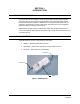
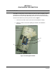
SECTION 3: CONFIGURING THE AVBPITPOS 3.1 DIP SWITCHES The AVBPIT1 is designed to interface different POS devices with the Rapid Eye system. The POS device and its related serial communication parameters are selected using three banks of DIP switches (S1, S2 and S3), which are found under the removable lid. Access the DIP switches by removing the lid as shown in Figure 4. 1. Unscrew the 2 screws used to secure the lid to the AVBPIT1 housing. 2.
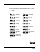
3.1 DIP SWITCHES, CONTINUED 3.1.1 DIP SWITCH S1 Use the S1 bank of DIP switches to select different operational modes for the AVBPIT1. Note: The dark area represents the desired setting of each individual switch within the DIP switch.
3.1 DIP SWITCHES, CONTINUED 3.1.3 DIP SWITCH S3 Consult your POS programming manual for baud rate and other serial port configuration parameters Use the S3 bank of DIP switches to change communication settings if they need to differ from the default settings of 9600, 8, N, 1 (All Switches off). This will configure the COM0 Channel of the AVBPIT1 module to match the printer or journal port settings required by the POS device.
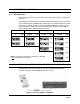
3.3 SETTING UP GILBARCO G-SITE® When setting up Gilbarco G-SITE®, follow these steps: 1. Leave S1 in the Debug mode (all switches OFF). 2. Set the Register output to a Citizen Printer (Printer not required.) 3. Set the Register Baud Rate to 9600. 4. Set S3 to Baud Rate Data Bits Stop Bit Parity Rev.
SECTION 4: SOFTWARE SETUP 4.1 SETTING UP RAPID EYE SOFTWARE 1. Start the Rapid Eye Multi VIEW program and connect to the Remote Unit. 2. Select Maintain from the top menu bar. 3. Select the Serial Devices tab from the Maintenance window. Rev.
4.1 SETTING UP RAPID EYE SOFTWARE, CONTINUED 4. Expand the New Devices section by clicking on the . 5. Select Data Input from New Devices and Drag and Drop onto Port 1. Rev.
4.1 SETTING UP RAPID EYE SOFTWARE, CONTINUED 6. Configure Port 1 – Data Input at: Baud Rate = 9600; Data Bits = 8; Stop Bits =1, Parity Bits = None 7. You can further customize the configuration by giving the Data Input a unique name, click in the Device Name field and enter a name for the POS device. Rev.
4.1 SETTING UP RAPID EYE SOFTWARE, CONTINUED 8. Once the device is configured, select Apply. 9. Select Yes in response to the Maintenance Message and wait for the System Operational message to appear in the Feedback dialogue box. Rev.
4.1 SETTING UP RAPID EYE SOFTWARE, CONTINUED 10. After System Operational feedback is received, test the communication between the AVBPITPOS and Rapid Eye by toggling DIP switch (S1) position 8 ON and OFF. Data window should display similar result as shown in the Panasonic window below. 11. You can further customize the configuration by setting up the Rules to create Log and Alarm events based on the data being captured by the Rapid Eye system. If Rules are not required, skip to Step 14. 12.
4.1 SETTING UP RAPID EYE SOFTWARE, CONTINUED 13. Once the rules are configured, select Apply then Yes in response to the Maintenance Message. Wait for the System Operational message to appear in the Feedback dialogue box. (Same procedure as described in steps 8 - 9). 14. From VIEW, initiate a Live session to the Remote Unit and verify that installation and setup are correct and that a separate data window is available for the POS device. Initiate a Live session to the Remote Unit.
4.1 SETTING UP RAPID EYE SOFTWARE, CONTINUED 15. Once installation and setup are complete and verified, replace and secure the lid to the AVBPIT1 module using the screws removed in Section 3.1. The AVBPITPOS installation is now complete. Rev.
SECTION 5: TROUBLESHOOTING 5.1 DIAGNOSTIC MODE Enter the Diagnostic Mode by setting all S1 DIP switches to the OFF position and cycling the power of the AVBPIT1 module ON S1 1 2 3 4 5 6 7 8 Diagnostic Mode Rapid Eye will display a message in the Data Input window similar to that shown below. Diagnostic Mode can also be used to pass unfiltered or generic ASCII data to the Rapid Eye system. 5.2 Rev.
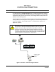
APPENDIX A: SYSTEM DIAGRAMS A.1 CONNECTING A POS SYSTEM WITH A SINGLE COM PORT See the figure below for a typical system diagram when connecting a POS device with a single COM port which will be shared between the printer and the AVBPIT1 module. POS-DB9 (TX) Pin 2 (SG) Pin 5 AVBPITPOS-DB9 (RX) Pin 3 (SG) Pin 5 921400-05 Figure 6: Connecting a POS device with a single COM port to the AVBPITPOS Rev.
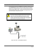
A.2 CONNECTING A POS SYSTEM WITH A SEPARATE COM PORT FOR PRINTER See the figure below for connecting a POS device with multiple COM ports enabled to the AVBPIT1 module. POS-DB9 (TX) Pin 2 (SG) Pin 5 AVBPITPOS-DB9 (RX) Pin 3 (SG) Pin 5 921400-05 Figure 7: Connecting a POS device with multiple COM ports to the AVBPITPOS Rev.
APPENDIX B: SYSTEM DIAGRAM USING B&B SMART SWITCH B.1 CONNECTING A POS SYSTEM USING B&B SMART SWITCH AND 4 AVBPITPOS MODULES This appendix is provided to document early uses of the AVBPITPOS in a multiple POS device configuration. By combining a B&B Smart Switch and 4 AVBPITPOS devices, it was possible to develop a multiple POS device system. The figure below depicts this basic system configuration attached to a Rapid Eye Multi Remote Unit.
Video Systems www.honeywellvideo.com 1-800-796-CCTV © 2004 Honeywell International Inc.