Buffered Smart Switch Model 232BSS4 Documentation Number: 232BSS4-2907 This product designed and manufactured in Ottawa, Illinois USA of domestic and imported parts by 707 Dayton Road -- P.O. Box 1040 -- Ottawa, IL 61350 USA Phone (815) 433-5100 -- General Fax (815) 433-5105 Phone (815) 433-5100 -- General Fax (815) 433-5105 Website: www.bb-elec.com Sales e-mail: orders@bb-elec.com -- Fax (815) 433-5109 Technical Support e-mail: support@bb.elec.
This document contains information that is proprietary and confidential to B&B Electronics Mfg. Co. Inc. The methods described herein are for the exclusive use of B&B Electronics authorized personnel. Any unauthorized use or dissemination of the information contained in the document is strictly forbidden. B&B Electronics Mfg Co Inc – 707 Dayton Rd - PO Box 1040 - Ottawa IL 61350 - Ph 815-433-5100 - Fax 815-433-5104 – www.bb-elec.
Table of Contents CHAPTER 1 – INTRODUCTION............................................................ 1 SPECIFICATIONS ........................................................................................ 2 DEFAULT PARAMETERS ............................................................................ 2 CHECKLIST ................................................................................................ 3 CHAPTER 2: OPERATION ....................................................................
ii Documentation Number 232BSS4-2907m B&B Electronics Mfg Co Inc – 707 Dayton Rd - PO Box 1040 - Ottawa IL 61350 - Ph 815-433-5100 - Fax 815-433-5104 – www.bb-elec.com B&B Electronics – Westlink Commercial Park – Oranmore, Galway, Ireland – Ph +353 91-792444 – Fax +353 91-792445 – www.bb-europe.
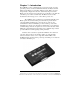
Chapter 1 – Introduction The 232BSS4 provides communications to four devices from one serial port. Each port uses a dedicated UART and includes an 8K byte transmit buffer and an 8K byte receive buffer (16K bytes total). Each port can be independently configured for data rate, data format, and protocol. The Master port can send and receive data from one of the Slave ports while the other Slave ports continue to buffer data.
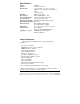
Specifications Model: Interface: Data Format: 232BSS4 RS-232 asynchronous 7 or 8 data bits, even, odd, or no parity (Master does not support 7 data bits with no parity) 1 stop bit (fixed) Data Rate: 1200 to 115.2 kbps Flow Control: Hardware(RTS/CTS) or None Power Requirements: +10 to +15 VDC @ 60 mA max. Power Connector: 2.
Checklist Examine the shipping carton and contents for physical damage. If damage is found, file a claim with the shipper immediately. The following equipment should be in the shipping carton: 1. RS-232 Buffered Smart Switch model 232BSS4 2. Instruction Manual 3. (2) 3.5" floppy disks If any of the items above are not in the shipping carton contact the shipper immediately.
4 Documentation Number 232BSS4-2907m B&B Electronics Mfg Co Inc – 707 Dayton Rd - PO Box 1040 - Ottawa IL 61350 - Ph 815-433-5100 - Fax 815-433-5104 – www.bb-elec.com B&B Electronics – Westlink Commercial Park – Oranmore, Galway, Ireland – Ph +353 91-792444 – Fax +353 91-792445 – www.bb-europe.
Chapter 2: OPERATION Symbols and Conventions Throughout this chapter of the manual, the following symbols and conventions will be used to clarify what type of data we are addressing. • Items enclosed in {brackets} will denote one byte. • A character in “quotes” will normally denote a printable ASCII character. A byte described in ALL CAPS is the ASCII description of a non-printable character. The abbreviation dec will denote a decimal value. The lower case letter h will be used to show a Hex value.
Port Configurations The 232BSS4 provides a dedicated UART to all five ports. This allows any port to be individually configured for baud rate, number of data bits, parity, and hardware (RTS/CTS) handshaking. Configuration of all the ports is done through the setup software. Baud Rate: Each port is configurable for the following baud rates: 1200 2400 4800 9600 19.2K 38.4K 57.6K or 115.2 kbps Data Bits: Each port can be configured for Seven or Eight data bits.
Smart Switch Only Mode Description: Smart Switch Only mode is used when the host device connected to the Master port initiates all communications with the Slave devices. To use the 232BSS4 as a Smart Switch Only, Auto Select is left unchecked in the setup software. In Smart Switch Only mode, the 232BSS4 is constantly looking for a command sequence by monitoring the data that is being received on the Master port from the host device.
Command Summary: Three Character Command Format: Char1 Char2 Command Char Control Char Control Char is only needed for Tx Only, Clear Buffer, and Ignore Commands Four Character Command Format: Char1 Char2 Char3 Command Char Control Char Control Char is only needed for Tx Only, Clear Buffer, and Ignore Commands Function Table 2.1 - 232BSS4 Command Summary Command Control Comments Char. Char.
Commands: Select Port A to transmit and receive – “A” Select Port B to transmit and receive – “B” Select Port C to transmit and receive – “C” Select Port D to transmit and receive – “D” The Select Port commands turn on the selected port for both transmit and receive operations. Once the command is received by the switch, any data that had been buffered from the selected Slave device will be sent to the Master.
A summary of the control characters for each combination of ports is given in Table 2.2. For instance, to broadcast to ports B & C, send: {Char1}{Char2}{Char3}”S”{Decimal 6} (B = 2, C = 4, 2 + 4 = 6) VB Example: BroadcastBC$ = CHR$(27) & CHR$(2) & “S” & CHR$(6) Clear Receive Buffer – “X” + one control byte specifying which ports’ buffers to clear. The Clear Buffer command will tell the 232BSS4 which Slave ports’ receive buffers to purge.
Table 2.
For instance, to ignore switching commands for 30 Seconds, send: {Char1}{Char2}{Char3}”T””7” VB Example: Ignore30s$ = CHR$(27) & CHR$(2) & “T” & “7” Table 2.3 - Timer Values Control Byte (ASCII) Control Byte (Decimal) Timer Setting “0” “1” “2” “3” “4” “5” “6” “7” “8” “9” 48 49 50 51 52 53 54 55 56 57 Timer disabled 10ms 25ms 100ms 500ms 1s 5s 30 s 1 min. 5 min.
commands and the Master can initiate the next communications sequence.
Auto Select/Smart Switch Mode Description Auto Select mode allows the Slave devices to initiate communications with the device connected to the Master port. When Auto Select mode is enabled through the setup software, the 232BSS4 passes data automatically from the Slaves to the Master. Each Slave port is buffered until the Master is available, then sent in turn.
When the specified Port Time has elapsed, the 232BSS4 checks in sequence for other Slave ports with buffered data and switches to them. If no other Slave ports need access to the Master, the current Slave port will again be connected until another Port Time has elapsed. Inactivity Time: The Inactivity Timer tracks how long a Slave port has been idle. The Inactivity Time is reset any time data is received on the connected Slave port or sent out the Master Port.
Using the 232BSS4 as a Buffered Splitter/Combiner The Auto Select and Initial Connection features of the 232BSS4 can be used to effectively create a data splitter. Data from the Master device can be shared with multiple Slave devices. Any data coming from the Slaves is buffered so that no data is lost. If the Slave devices already include an address or identifier, no software changes are required. Figure 2.1 shows a typical configuration allowing several serial terminals access to the same host.
Back to Back Operation (mux/demux) Printer Port A Port B Port C Port D 232BSS4 MASTER PORT +12 VDC POWER MANUFACTURING COM PANY www.bb-elec.com Ottawa, IL 61350 USA 232BSS4 Modem or MASTER PORT Modem M ANUFACTURING COMPANY www.bb-elec.com Ottawa, IL 61350 USA or B&B elect ronics B&B elect ronics +12 VDC POWER Printer Port A Port B Port C Port D PC Measurement 78.6 Direct Cable Connection 78.6 Measurement 78.6 78.6 RF Modem Scale Scale RF Modem PC Figure 2.2.
Cascading Multiple Switches If you have more than four devices that are sending data, more than one 232BSS4 can be cascaded, allowing more ports to be added. The 232BSS4 buffers data from all ports at once, making it well suited for devices that will send a fixed amount of data at sporadic intervals, such as measurement instruments, security access card readers, barcode scanners, or time clocks. Below is an explanation of how best to utilize the 232BSS4 to connect these devices to your PC.
Figure 2.3 shows a typical setup, with 16 devices sending information at random times to the PC. The switches at Level 2 receive the data and send it on to the Level 1 switch. The Level 1 switch buffers the data and sends it to the PC. Each of the switches will automatically send the data when it is available. If another port has access to the PC, the data will be buffered until a path is available.
Slave Devices that Require Polling: This configuration will also work with systems where the devices have to be polled for information. With the setup of Figure 2.3, the switches can be configured so that you still only have to send one set of switching characters. To do this, set the switches up in the following way: • Set the switch on Level 1 to broadcast to all slaves on startup. • Set the switch on Level 1 to Auto Select mode, no preamble.
Chapter 3: PORT CONNECTIONS DTE/DCE Explanation In order to determine the proper port connections to the 232BSS4, it is necessary to have a basic understanding of the terms DTE and DCE. RS232 was designed, using DB-25 connectors, for connecting a DTE (Data Terminal Equipment) device to a DCE (Data Communication Equipment) device. Each device will have inputs on pins that correspond to outputs on the same pins of the other device.
Master Port Connections: The Master Port of the 232BSS4 is a 25 pin female D-sub connector configured as a DCE. This provides direct connection to an IBM PC compatible or other DTE device. When connecting the Master port to a modem, the Master port of another 232BSS4, or other device configured as a DCE, a null modem adapter such as B&B’s model 232DTE is needed.
Chapter 4: SETUP SOFTWARE Introduction The 232BSS4 comes with simple setup software for configuring the switch. The software can be run on any PC compatible computer running Microsoft Windows 95, 98, NT, 2000, XP or Vista operating system. Once the switch is configured, all parameters are saved in non-volatile memory so the switch can be powered down and used anywhere without the loss of configuration data.
Software Installation The setup software for the 232BSS4 must be installed on your hard drive before it can be run. All directions assume the CDROM drive is assigned to drive D. If your drive is assigned another drive name, replace that name for D in the instructions. To install on your hard drive follow these steps: • • • • Place the 232BSS4 setup CDROM in drive D. Select RUN from the Windows START menu. Type D:\SETUP and click OKAY. Follow the instructions in the Installation program.
Setup Tutorial Step 1: Start the software by double clicking the Smart Switch setup icon on the desktop. Step 2: Select the serial (COM) port that will be used to configure the 232BSS4 or Check the box to create a configuration file without the 232BSS4 connected. Step 3: Click Next Step 4: If you are creating a configuration without a switch connected, proceed to “Single Unit Main screen.” Otherwise, select the way that the 232BSS4 will be used.
between 0 and 65000 (65 seconds). See chapter 2 for a full description of these Timeout values. Initial Connections: When selected, the Initial Connections button provides a selection of ports to be connected when the unit is powered up. When the switch is set for Smart Switch Only mode (no Auto Select), the Master to Slave communications (individual or broadcast) can be initialized to any or all of the four slave ports. One of the Slaves can also have access to the Master on power-up.
Configure Switch Button: This button will save all changes to the connected switch. NOTE: Once changes are saved to the switch they cannot be reset automatically. Be sure to review all changes before saving using the View Module Configuration button. Run Self Test: The 232BSS4 is programmed with a Self Test mode. The microprocessor checks the UARTs, RAM, and EEPROM and reports any errors back to the setup software. If the software reports an error, contact B&B Technical Support.
#2 tab is selected. The user should not have to reload the configuration except when the parameters need to be reset to those already saved in the switch. The load configuration button will load the configuration from the connected switch and assume these apply to the selected Unit. View Module Configuration: Each unit’s configuration can be reviewed on one screen by selecting the appropriate tab and clicking the View Module Configuration button.
Copying Parameters Between Switches: The 232BSS4 setup software can save configuration data to a file for copying of parameters. Any unit’s setup can be copied by first reading the data from one switch, then saving to another. Step 1: Run the setup software. Step 2: Select serial (COM) port to be used for programming. Step 3: Select Single Unit operation. If the configuration to be used is already saved to a file, skip to Step 8. Step 4: Connect the switch to be copied to the serial (COM) port of the PC.
30 Documentation Number 232BSS42907 Manual B&B Electronics Mfg Co Inc – 707 Dayton Rd - PO Box 1040 - Ottawa IL 61350 - Ph 815-433-5100 - Fax 815-433-5104 B&B Electronics Ltd – Westlink Commercial Park – Oranmore, Galway, Ireland – Ph +353 91-792444 – Fax +353 91-792445
Appendix A: ASCII Character Codes DECIMAL to HEX to ASCII CONVERSION TABLE DEC HEX ASCII KEY DEC HEX ASCII DEC HEX ASCII DEC HEX ASCII 0 0 NUL ctrl @ 32 20 SP 64 40 @ 96 60 ` 1 1 SOH ctrl A 33 2 2 STX ctrl B 34 21 ! 65 41 A 97 61 a 22 “ 66 42 B 98 62 3 3 ETX ctrl C b 35 23 # 67 43 C 99 63 4 4 EOT c ctrl D 36 24 $ 68 44 D 100 64 d 5 5 6 6 ENQ ctrl E 37 25 % 69 45 E 101 65 e ACK ctrl F 38 26 & 70 46 F 102 66 7 f 7 BEL
A-2 Appendix A Documentation Number 232BSS42907 Manual B&B Electronics Mfg Co Inc – 707 Dayton Rd - PO Box 1040 - Ottawa IL 61350 - Ph 815-433-5100 - Fax 815-433-5104 B&B Electronics Ltd – Westlink Commercial Park – Oranmore, Galway, Ireland – Ph +353 91-792444 – Fax +353 91-792445
Appendix B: Cable Charts All charts give full pin outs. Only pins 2 & 3 are required for basic operation. Handshaking pins are needed for hardware (RTS/CTS) handshaking or if DTR is to be used to signal the Master port to accept commands. See Appendix C for a block diagram of the 232BSS4. Master Port Connections: Chart B.1.
2 <----------- 3 (RD) 3 -----------> 2 (TD) 4 -----------> 20 (DTR) * 5 <---------> 7 (GND) 6 <----------- 6 (DSR) * 7 -----------> 4 (RTS) 8 <----------- 5 (CTS) * - Pins 6, 8, & 20 looped back internally on the 232BSS4 B-2 Appendix B: Cable Charts Documentation Number 232BSS42907 Manual B&B Electronics Mfg Co Inc – 707 Dayton Rd - PO Box 1040 - Ottawa IL 61350 - Ph 815-433-5100 - Fax 815-433-5104 B&B Electronics Ltd – Westlink Commercial Park – Oranmore, Galway, Ireland – Ph +353
Chart B.3. DCE (Modem) DB25 Connector to Master Port • DCE (Modem) Serial Port DB25 Connector 2 Signal Direction <----------- 3 -----------> 4 <----------- 5 -----------> 6 -----------> 7 <---------> 20 <----------- 232BSS4 Master Port (DCE) DB25 Connector 3 (RD) 2 (TD) 5 (CTS) 4 (RTS) 20 (DTR) * 7 (GND) 6 (DSR) * - Pins 6, 8, & 20 looped back internally on the 232BSS4 Chart B.4.
• - Pins 6, 8, & 20 looped back internally on the 232BSS4 Slave Port Connections: Chart B.5. Ports A - D (DTE) to DTE (PC) DB25 Connector 232BSS4 Ports A - D (DTE) DB9 Connector 1 (DCD) * 2 (RD) 3 (TD) 4 (DTR) * 5 (GND) 6 (DSR) * 7 (RTS) 8 (CTS) Signal Direction ----------> <-------------------> ----------> <--------> <-------------------> <---------- DTE (PC) Serial Port DB25 Connector 8 2 3 6 7 20 5 4 * - Pins 1, 4, & 6 looped back internally on the 232BSS4 Chart B.6.
1 (DCD) * 2 (RD) 3 (TD) 4 (DTR) * 5 (GND) 6 (DSR) * 7 (RTS) 8 (CTS) • <---------<-------------------> ----------> <--------> <-------------------> <---------- 8 3 2 20 7 6 4 5 - Pins 1, 4, & 6 looped back internally on the 232BSS4 Chart B.8.
B-6 Appendix B: Cable Charts Documentation Number 232BSS42907 Manual B&B Electronics Mfg Co Inc – 707 Dayton Rd - PO Box 1040 - Ottawa IL 61350 - Ph 815-433-5100 - Fax 815-433-5104 B&B Electronics Ltd – Westlink Commercial Park – Oranmore, Galway, Ireland – Ph +353 91-792444 – Fax +353 91-792445
Appendix C: Block Diagram PORT D TD RD RTS CTS DSR DCD DTR GND 3 2 7 8 6 1 4 5 PORT C UART TD RD RTS CTS DSR DCD DTR GND 3 2 7 8 6 1 4 5 PORT B UART TD RD RTS CTS DSR DCD DTR GND 3 2 7 8 6 1 4 5 PORT A 3 2 7 8 6 1 4 5 UART Microcontroller GND UART 64K RAM DTR UART 2 3 4 5 6 8 20 7 MASTER TD RD RTS CTS DSR DCD TD RD RTS CTS DSR DCD DTR GND 232BSS4 Block Diagram Documentation Number 232BSS42907 Manual Appendix C B&B Electronics Mfg Co Inc – 707 Dayton Rd - PO Box 1040 - Ottawa IL 6
C-2 Appendix C Documentation Number 232BSS42907 Manual B&B Electronics Mfg Co Inc – 707 Dayton Rd - PO Box 1040 - Ottawa IL 61350 - Ph 815-433-5100 - Fax 815-433-5104 B&B Electronics Ltd – Westlink Commercial Park – Oranmore, Galway, Ireland – Ph +353 91-792444 – Fax +353 91-792445
Appendix D: Declaration of Conformity DECLARATION OF CONFORMITY Manufacturer’s Name: Manufacturer’s Address: Model Numbers: Description: Type: Application of Council Directive: Standards: B&B Electronics Manufacturing Company P.O. Box 1040 707 Dayton Road Ottawa, IL 61350 USA 232BSS4 RS-232 4-Port Buffered Smart Switch Light industrial ITE equipment 89/336/EEC EN 55022 EN 61000-6-1 EN 61000 (-4-2, -4-3, -4-4, -4-5, -4-6, -4-8, -4-11) William H.