This manual covers the following B&B Electronics' model serial cards: RS-232 Serial Cards 232CC1A 232CC2A CE 232CC1B 232CC2B Documentation Number 232CCxx4502 Each of these models is an RS-232 serial card and uses the same printed circuit board. The "1" and "2" suffix designates the number of ports on the card. The model number of the card is printed on a sticker on the board.
Table of Contents Chapter 1: Introduction and General Information ...........1 Features ................................................................................1 Specifications ........................................................................1 RS-232 Transceiver ........................................................2 Power Consumption (2-port model) ................................2 Chapter 2: Quick Installation Guide..................................3 Chapter 3: Windows Installation ......
Chapter 1: Introduction and General Information The B&B Electronics’ 232CC series RS-232 serial interface cards are designed for the IBM PC, XT, AT and compatibles. Ports are configured as a standard DTE device, and connections are made on 9-pin D-style connectors. The 232CC cards offer exceptional setup flexibility. The 232CC series has the ability to use any I/O address and any hardware interrupt. You can install as many serial ports as will physically fit in a machine.
RS-232 Transceiver TD and RD Device: DS232AS Transmitter output voltage: ±5.0 V minimum Short circuit current: ±30 mA typical Input low level threshold voltage: 0.8 V minimum Input high level threshold voltage: 2.4V maximum Device will withstand ±30 V Handshake Line Device: SN75185 Transmitter output voltage: ±10.0 V minimum Short circuit current: ±12 mA typical Input low level threshold voltage: 0.65 V minimum Input high level threshold voltage: 2.
Chapter 2: Quick Installation Guide The following steps will help you install the Model 232CCXX Serial Card. Please follow (step-by-step) the numbered instructions and refer to any corresponding chapters for more details. CAUTION: Electrostatic Sensitive Device. Use ESD precautions for safe handling.
4. Assign Address and IRQ – The address and IRQ are set in the operating system that you are using. This is the final step of adding new hardware. See Chapter 4 for more details. 5. Set up the address (with dipswitches) and IRQ (jumpers) on the serial card to reflect unused addresses and IRQ’s that you want to use. The address dipswitch setting consists of configuring seven dipswitches that reflect a particular hex address. The IRQ is set via a little black jumper.
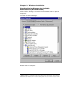
Chapter 3: Windows Installation Checking Device Manager for Available Address/IRQ’s (Windows 95/98) Click on Start / Settings / Control Panel and double-click on System Properties. Left-click on Device Manager. Double-click on Computer. Documentation Number 232CCxx4502 5 B&B Electronics Mfg Co – 707 Dayton Rd - PO Box 1040 - Ottawa IL 61350 - Ph 815-433-5100 - Fax 815-433-5104 B&B Electronics Ltd – Westlink Comm.
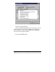
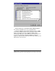
Left-click on Interrupt Request. Find a free IRQ in the displayed list. Any number that is seen on the left hand side of this screen is an IRQ that is currently being used. The object is to find a number of IRQ(s) that are not listed and set your port(s) using those IRQ’s. Left-click on Input/Output (I/O). 6 Documentation Number 232CCxx4502 B&B Electronics Mfg Co – 707 Dayton Rd - PO Box 1040 - Ottawa IL 61350 - Ph 815-433-5100 - Fax 815-433-5104 B&B Electronics Ltd – Westlink Comm.
Scroll through the list, check 03F8H, 02F8H, 03E8H, 02E8H. If one of these is available, use it. If not, check alternates. Find a free address in the list. Most desktop PC’s have a COM1 and possibly a COM2 already on their system which will be seen in the list. You might have to start at COM3 or COM4 to begin addressing the ISA card. If these addresses are used you may have to resort to the Frequently Unused Port Addresses (found in Chapter 4, Table 3) of this manual.
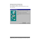
Adding Serial Port(s) in Windows 95/98 Go to Start Menu / Settings / Control Panel. Run the Windows Add New Hardware utility found in the control panel. Click Next. 8 Documentation Number 232CCxx4502 B&B Electronics Mfg Co – 707 Dayton Rd - PO Box 1040 - Ottawa IL 61350 - Ph 815-433-5100 - Fax 815-433-5104 B&B Electronics Ltd – Westlink Comm.
Click Next. Select Yes/No, (for) the device in the list. Click Next. Documentation Number 232CCxx4502 9 B&B Electronics Mfg Co – 707 Dayton Rd - PO Box 1040 - Ottawa IL 61350 - Ph 815-433-5100 - Fax 815-433-5104 B&B Electronics Ltd – Westlink Comm.
Select No (you do not want Windows to search for your new hardware). Click Next. Select Ports (COM & LPT). Click Next. 10 Documentation Number 232CCxx4502 B&B Electronics Mfg Co – 707 Dayton Rd - PO Box 1040 - Ottawa IL 61350 - Ph 815-433-5100 - Fax 815-433-5104 B&B Electronics Ltd – Westlink Comm.
Select (Standard port types) and Communication Port. Click Next. Documentation Number 232CCxx4502 11 B&B Electronics Mfg Co – 707 Dayton Rd - PO Box 1040 - Ottawa IL 61350 - Ph 815-433-5100 - Fax 815-433-5104 B&B Electronics Ltd – Westlink Comm.
The next screen will show the address and interrupt request of the port. These may not match your configuration. For now, simply click Next. Windows may ask for the Windows 95/98 disk/CD to be inserted. Finally, click Finish. 12 Documentation Number 232CCxx4502 B&B Electronics Mfg Co – 707 Dayton Rd - PO Box 1040 - Ottawa IL 61350 - Ph 815-433-5100 - Fax 815-433-5104 B&B Electronics Ltd – Westlink Comm.
Changing COM Port Resources in Windows 95/98 Click Start / Settings / Control Panel and double-click on System Properties. Click on Device Manager (make sure “View devices by type” is enabled. Double-click on Ports (COM & LPT). Documentation Number 232CCxx4502 13 B&B Electronics Mfg Co – 707 Dayton Rd - PO Box 1040 - Ottawa IL 61350 - Ph 815-433-5100 - Fax 815-433-5104 B&B Electronics Ltd – Westlink Comm.
Double-click on the new port that has been added. Click Resources. 14 Documentation Number 232CCxx4502 B&B Electronics Mfg Co – 707 Dayton Rd - PO Box 1040 - Ottawa IL 61350 - Ph 815-433-5100 - Fax 815-433-5104 B&B Electronics Ltd – Westlink Comm.
Click off (check mark out of box) Use Automatic Settings. Select Basic Configuration 0007 (or last one). Select Input / Output Range. Click Change Setting. Change Address to match the free address settings you found earlier. Click OK. Select Interrupt Request. Click Change Settings. Change IRQ to match the free IRQ settings you found earlier. At this point you can shut down the system and physically install your B&B Electronics Serial Card into an available ISA slot.
Checking Windows NT Diagnostics for Available Address/IRQ’s (Windows NT 4.0) Click on Start / Programs / Administrative Tools / Windows NT Diagnostics. Left-click on Resources. Find a free IRQ in the following list. Any number that is seen on the left hand side of this screen is an IRQ that is currently being used. The object is to find a number of IRQ(s) not listed and set your port(s) using those IRQ’s. Left-click on I/O Port in Resources. Tab to view currently used addresses.
Scroll through the list, checking 03F8H, 02F8H, 03E8H, 02E8H. If one of these is available, use it. If not, check alternates. Find a free address in the list. Most desktop PC’s have a COM1 and possibly a COM2 already on their system, which will be seen in the list. You may have to start at COM3 or COM4 to start your addressing of the ISA card you have. If these addresses are used you may have to resort to the Frequently Unused Port Addresses (found in Chapter 4, Table 3) of this manual.
Adding Serial Port(s) in Windows NT 4.0 Go to Start Menu / Settings / Control Panel. Double-click on Ports. Click Add. Choose COM Port Number, Base I/O Address, and IRQ that you want to use for the new Serial Port(s) being added. After clicking OK, you will see a screen – System Setting Change. Click the button Restart Now to restart Windows NT 4.0. At this point you can shut down the system and physically install your B&B Electronics Serial Card into an available ISA Slot.
Checking Windows 2000 for Available Address/IRQ’s Click on Start / Settings / Control Panel. Double-click on System. Documentation Number 232CCxx4502 19 B&B Electronics Mfg Co – 707 Dayton Rd - PO Box 1040 - Ottawa IL 61350 - Ph 815-433-5100 - Fax 815-433-5104 B&B Electronics Ltd – Westlink Comm.
Click on Hardware. 20 Documentation Number 232CCxx4502 B&B Electronics Mfg Co – 707 Dayton Rd - PO Box 1040 - Ottawa IL 61350 - Ph 815-433-5100 - Fax 815-433-5104 B&B Electronics Ltd – Westlink Comm.
Click on Device Manager. Documentation Number 232CCxx4502 21 B&B Electronics Mfg Co – 707 Dayton Rd - PO Box 1040 - Ottawa IL 61350 - Ph 815-433-5100 - Fax 815-433-5104 B&B Electronics Ltd – Westlink Comm.
Click on View (top of screen). Click on Resources by type. Double-click on Input/Output. Find an unused address to set your B&B Electronics serial card to. Scroll through the list, checking 03F8H, 02F8H, 03E8H, 02E8H. If one of these is available, use it. If not, check alternates. Find a free address in the list. Most desktop PC’s have a COM1 and possibly a COM2 already on their system, which will be seen in the list. You may have to start at COM3 or COM4 to begin addressing the ISA card that you have.
Double-click on Interrupt Request (IRQ). Here you need to find an unused IRQ to set your B&B Electronics serial card to. Documentation Number 232CCxx4502 23 B&B Electronics Mfg Co – 707 Dayton Rd - PO Box 1040 - Ottawa IL 61350 - Ph 815-433-5100 - Fax 815-433-5104 B&B Electronics Ltd – Westlink Comm.
Adding Serial Port(s) in Windows 2000 Go to Start Menu / Settings / Control Panel. Double-click on Add/Remove Hardware. 24 Documentation Number 232CCxx4502 B&B Electronics Mfg Co – 707 Dayton Rd - PO Box 1040 - Ottawa IL 61350 - Ph 815-433-5100 - Fax 815-433-5104 B&B Electronics Ltd – Westlink Comm.
Click Next. Click on Add/Troubleshoot a device. Click Next. The following screen will appear after a few seconds. Documentation Number 232CCxx4502 25 B&B Electronics Mfg Co – 707 Dayton Rd - PO Box 1040 - Ottawa IL 61350 - Ph 815-433-5100 - Fax 815-433-5104 B&B Electronics Ltd – Westlink Comm.
Click Add a new device. Click Next. Click No, I want to select the hardware from a list. 26 Documentation Number 232CCxx4502 B&B Electronics Mfg Co – 707 Dayton Rd - PO Box 1040 - Ottawa IL 61350 - Ph 815-433-5100 - Fax 815-433-5104 B&B Electronics Ltd – Westlink Comm.
Click Ports (COM & LPT). Click Next. Select Standard port types and Communication Port and Click Next. You will see the following screen, go ahead and Click OK. Documentation Number 232CCxx4502 27 B&B Electronics Mfg Co – 707 Dayton Rd - PO Box 1040 - Ottawa IL 61350 - Ph 815-433-5100 - Fax 815-433-5104 B&B Electronics Ltd – Westlink Comm.
The Resources area will allow you to set the IRQ and Address of your new ports. Click on the down arrow to the middle right of the screen after “Setting based on”: Click on the highest Basic configuration number in the list on the “Setting based on” category. 28 Documentation Number 232CCxx4502 B&B Electronics Mfg Co – 707 Dayton Rd - PO Box 1040 - Ottawa IL 61350 - Ph 815-433-5100 - Fax 815-433-5104 B&B Electronics Ltd – Westlink Comm.
Double-click on the Input/Output Range to set the Address. Double-click on the Interrupt Request to set the IRQ. Select IRQ and Address that you want your port(s) configured at. Documentation Number 232CCxx4502 29 B&B Electronics Mfg Co – 707 Dayton Rd - PO Box 1040 - Ottawa IL 61350 - Ph 815-433-5100 - Fax 815-433-5104 B&B Electronics Ltd – Westlink Comm.
At this point you can shut down the system and physically install your B&B Electronics Serial Card into an available ISA Slot. Double check to make sure the addresses and IRQ’s on the Serial Card are set to the correct settings. 30 Documentation Number 232CCxx4502 B&B Electronics Mfg Co – 707 Dayton Rd - PO Box 1040 - Ottawa IL 61350 - Ph 815-433-5100 - Fax 815-433-5104 B&B Electronics Ltd – Westlink Comm.
Chapter 4: Address and IRQ Setting Address Switch Setup A Windows PC has I/O port addresses and memory addresses. Some devices use both types of addresses. I/O port addresses have a 64K address space. Devices may decode all 16 address bits or only some of the lower bits. Traditionally, serial cards have only decoded 10 bits of the address bus. Recently this has begun to cause address conflicts with full 16 bit decoded devices, most notably between video cards and COM 4.
Figure 1. Silk Screen Plot of 232CC PCB 32 Documentation Number 232CCxx4502 B&B Electronics Mfg Co – 707 Dayton Rd - PO Box 1040 - Ottawa IL 61350 - Ph 815-433-5100 - Fax 815-433-5104 B&B Electronics Ltd – Westlink Comm.
When setting the address (via the dipswitch) use the silkscreen on the printed circuit board. This silkscreen shows a “1” and a “0” -referring to the “on and “off” states that each switch is set to. Switch S1 configures port one (labeled J1) and, on two port cards, switch S2 configures port two (labeled J2). Least significant bit (LSB) and most significant bit (MSB) are labeled on the card. Table 1 shows the numerical weight and electrical connection of each switch position.
Table 3.
Chapter 5: Communication Jumper Settings This chapter will cover all of the jumper settings to set your B&B Serial Card for the proper communications that you desire. CAUTION : Electrostatic Sensitive Device. Use ESD precautions for safe handling. High Speed Mode The 232CC Serial has only two communication jumpers referring to clock speed. High data rates may be obtained with the 232CC cards by placing JP1 or JP2 in the *2 position. This multiplies the clock speed supplied to the UARTs by 2 times to 3.
Chapter 6: Physical Hook-up and Troubleshooting This chapter will cover 232CC pinout, communication cable data, and troubleshooting information. Pinouts The 232CC Serial Cards are wired as DTE (Data Terminal Equipment) devices. The 232CC Serial Cards can be connected directly to DCE (Data Communication Equipment) devices with a straight through cable. If you need to connect two DTE devices, you will need a null modem cable or cross-over cable.
Troubleshooting If you are unable to communicate with the card from your software: 1. Consult your software manual to make sure it supports the address and interrupt that you have configured. 2. Double check that the address and interrupt are properly set. 3. Try another software package for troubleshooting. Download SimpTerm (DOS Terminal Emulator) or Comtest (Windows Terminal Emulator) from B&B Electronics’ web site.
Appendix A: Hardware I/O Map I/O Map of XT Class Machines Hex Address 000-00F 020-021 040-043 060-063 080-083 0A0-0AF 200-20F 210-217 2E8-2EF 2F8-2FF 300-31F 320-32F 378-37F 380-38F 3B0-3BF 3D0-3D7 3E8-3EF 3F0-3F7 3F8-3FF Address Function in XT Class Machines DMA controller (8237A) interrupt controller (8259A) timer (8253) PPI(8255A) DMA page register (74LS612) NMI - non maskable interrupt game port joystick controller expansion unit COM4 serial port COM2 serial port prototype card hard disk parallel print
I/O Map of AT Class Machines Hex Address Address Function in AT Class Machines 000-01F DMA controller #1 (8237A-5) 020-03F interrupt controller #1 (8259A) 040-05F timer (8254) 060-06F keyboard (8042) 070-07F NMI - non maskable interrupt & CMOS RAM 080-09F DMA page register (74LS612) 0A0-0BF interrupt controller #2 (8259A) 0C0-0DF DMA controller #2 (8237A) 0F0-0FF 80287 math coprocessor 1F0-1F8 hard disk 200-20F game port joystick controller 258-25F Intel Above Board 278-27F parallel printer port 2 2E8-2EF C
Appendix B: Declaration of Conformity Statement DECLARATION OF CONFORMITY Manufacturer’s Name: Manufacturer’s Address: Model Numbers: Description: Type: Application of Council Directive: Standards: B&B Electronics Manufacturing Company P.O. Box 1040 707 Dayton Road Ottawa, IL 61350 USA 232CC1A, 232CC1B, 232CC2A, 232CC2B RS-232 Serial Cards Light industrial ITE equipment 89/336/EEC EN 50082-1 EN 61000 (-4-2, -4-3, -4-4, -4-6) William H.