
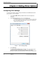
Specifications


Serial Card Setup
8 Chapter 2 Document Number 3PCI-0712m
multipoints) the transmitter can be enabled all the time. Placing the middle DIP switch in
the TX ON position accomplishes this.
For RS-485 operation the middle DIP switch is placed in the TX SD position. In this
position the transmitter is only enabled when data is being sent. The transmitter is tri-
stated when not sending data, allowing other transmitters on the communications line to
transmit without interference.
DIP Switch 3 (RS-232/422/485 ports)
The bottom DIP switch (3) configures the port for half-duplex (two-wire) RS-485
operation or full-duplex (four wire) RS-422/RS-485 operation. Placing the bottom DIP
switch in the RX ON position configures the port for four wire operation. In this mode the
receiver is continuously enabled, allowing it to receive all data on the communications
line. Since the transmitter sends data on the other wire pair the port does not receive its
own transmissions.
Placing the bottom DIP switch in the RX position configures the port for two wire
operation. In this mode the transmitter and receiver are connected to the same wire
pair. The receiver is disabled when its transmitter is sending, preventing the port from
receiving its own data.
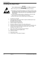
Setting the DIP Switches on RS-422/485 Only Ports
The 3PCIOU4 MIport card provides a combination of RS-232/422/485 and RS-422/485
only ports. Ports that do not include RS-232 operation use double DIP switches rather
than triple DIP switches. These DIP switches operate the same as the two bottom DIP
switches in the RS232/422/485 ports.
TX On
RX On
TX SD
RX SD
Switch 1
Switch 2
RS-422 Mode
TX On
RX On
TX SD
RX SD
4-wire RS-485 Mode
TX On
RX On
TX SD
RX SD
2-wire RS-485 Mode
Figure 6. RS-422/485 only DIP Switch Settings