
User Guide


485SDD16-1005 Manual 5
B&B Electronics -- 707 Dayton Road -- Ottawa, IL 61350
PH (815) 433-5100 -- FAX (815) 433-5104
Chapter 2 - Connections
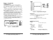
This chapter will cover the connections required for the
485SDD16. There are three sets of connections: digital I/O, serial
port, and power supply. Do not make any connections to the
485SDD16 until you have read this chapter.
Digital I/O Connections
Connections to the I/O lines are made through the DB25S
(female) I/O port connector. Refer to Table 2.1. See Chapter 5 for
I/O interfacing examples.
Digital Inputs
The digital input lines are CMOS/TTL compatible and can handle
voltages from 0Vdc to +5Vdc.
Digital Outputs
The digital output lines have a maximum voltage of +5Vdc and
are CMOS compatible.
Ground
This pin should be connected to the external digital devices
ground.
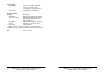
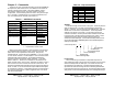
Table 2.1 - 485SDD16 I/O Port Pinout
DB-25S
Pin #
Function
DB-25S
Pin #
Function
1 No connection 14 I/O #15
2 No connection 15 I/O #14
3 No connection 16 I/O #13
4 No connection 17 I/O #12
5 No connection 18 I/O #11
6 No connection 19 I/O #10
7 Ground 20 No connection
8 +12Vdc Input 21 I/O #9
9 I/O #0 22 I/O #8
10 I/O #1 23 I/O #7
11 I/O #2 24 I/O #6
12 I/O #3 25 I/O #5
13 I/O #4
6 485SDD16-1005 Manual
B&B Electronics -- 707 Dayton Road -- Ottawa, IL 61350
PH (815) 433-5100 -- FAX (815) 433-5104
Serial Port Connections
In order to communicate to the 485SDD16 module it must be
connected to an RS-422/RS-485 serial port. The 485SDD16 will
work on a 2-wire or 4-wire RS-485 multi-node network. Refer to
B&B Electronics’ free RS-422/485 Application Note for more
information. The unit automatically detects baud rates from 1200 to
9600. A data format of 8 data bits, 1 stop bit and no parity is used.
Connections are made using terminal blocks. Table 2.2 shows the
terminal blocks and their functions.
A typical 2-wire RS-485 connection is shown in Figure 2.3 and a
typical RS-422 (or RS-485 4-wire) connection is shown in Figure
2.4. Note that the 485SDD16 data line labels use “A” and “B”
designators (per EIA RS-485 Specification). However, some RS-485
equipment uses “+” and “-“ as designators. In almost all cases, the
“A” line is the equivalent of the “-“ line and the “B” is the equivalent of
the “+” line. With an RS-485/422 system there are other factors that
require consideration, such as termination and turn-around delay.
For more information refer to B&B Electronics’ free RS-422/485
Application Note.
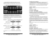
Table 2.2 - RS-485 Terminal Block Connections
TB
Label
Signal
Signal
Direction at
485SDD16
Notes
FR
GND
Frame
Ground
- Connection for frame ground.
TD(A) Transmit
Data (A)
Output Connection is required. [Loop to
RD(A) for 2-wire hookup]
TD(B) Transmit
Data (B)
Output Connection is required. [Loop to
RD(B) for 2-wire hookup]
RD(A) Receive
Data (A)
Input Connection is required. [Loop to
TD(A) for 2-wire hookup]
RD(B) Receive
Data (B)
Input Connection is required. [Loop to
TD(B) for 2-wire hookup]
+12V +12 Vdc
Power
Input Connection is required.
GND Ground - Connection for Signal GND and
Power Supply GND.