8 Port Smart Switch CE Model 232D4SS8 Documentation Number 232D4SS84502 This product designed and manufactured in Ottawa, Illinois USA of domestic and imported parts by International Headquarters B&B Electronics Mfg. Co. Inc. 707 Dayton Road -- P.O. Box 1040 -- Ottawa, IL 61350 USA Phone (815) 433-5100 -- General Fax (815) 433-5105 Home Page: www.bb-elec.com Sales e-mail: orders@bb-elec.com -- Fax (815) 433-5109 Technical Support e-mail: support@bb.elec.
TABLE OF CONTENTS Chapter 1: HARDWARE ......................................................1 Introduction............................................................................1 Specifications ........................................................................2 Checklist ................................................................................3 Serial Data Configuration ......................................................3 Port Configuration...............................................
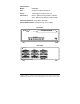
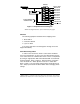
Chapter 1: HARDWARE Introduction The RS-232 Eight Port Smart Switch (232D4SS8) allows one RS-232 host device to connect to eight asynchronous serial devices. Refer to Figure 1. Four RS-232 ports and four RS-232 or RS-485 (two or four wire, send data contol) are standard on the 232D4SS8, depending on the pins you use. Other options and additional RS-422/485 ports are available by contacting B&B technical support. Ports configured as RS-232 support signals TD, RD, RTS, CTS, DTR, and DSR or CD.
Specifications Model: 232D4SS8 Size: 25.65 W x 19.05 D x 8.38 H cm Power: 12VAC 830mA, 2.5mm power jack Connectors: Master - DB-25 female (RS-232 or RS-422) Slave - DB-25 male (RS-232 or RS-422/485) Switching Baud Rate: From 300 to 38.4 Kbps Connected Baud Rate: Any baud rate up to 115.
Switch Control Master Port TD UART Microcontroller Port Combiner Control Lines Ports "A-H" TD Port A TD Port B TD Port C TD Port D TD Port E TD Port F TD Port G TD Port H CTS Port A CTS Port H Figure 1. Simplified Functional Diagram NOTE: This diagram illustrates only the transmit data (TD) signal. Checklist The following equipment should be in the shipping carton: 1. Smart Switch 2. Instruction Manual 3. (2) 3 1/2" disks If any of the items above are damaged or missing contact the shipper immediately.
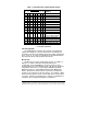
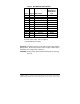
Table 1. Communication & Configuration Switch 1 2 0 0 1 0 0 1 1 1 0 0 1 0 0 1 1 1 X X X X X X X X DIP Switch 1 3 4 5 6 7 8 0 0 X X X X 0 0 X X X X 0 0 X X X X 0 0 X X X X 1 0 X X X X 1 0 X X X X 1 0 X X X X 1 0 X X X X X X 0 X X X X X 1 X X X X X X 0 X X X X X 1 X X Setting 300 Baud 600 Baud 1200 Baud 2400 Baud 4800 Baud 9600 Baud * 19.2K Baud 38.4K Baud 8 Data Bits * 7 Data Bits Smart Switch Mode * Smart Switch and Port Combiner Mode X X X X X X 0 X 3 Char. Command * X X X X X X 1 X 4 Char.
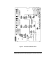
Figure 2. Printed Circuit Board Outline Documentation Number 232D4SS84502 Manual 5 B&B Electronics Mfg Co – 707 Dayton Rd - PO Box 1040 - Ottawa IL 61350 - Ph 815-433-5100 - Fax 815-433-5104 B&B Electronics Ltd – Westlink Comm.
Figure 3. Master Port DCE/DTE Jumpers Figure 4. PC Board Options for RS-485 If an IBM PC (DTE device) is connected to the 232D4SS8 Master port, the Master port should be configured as a DCE port. If a modem (DCE device) is connected to the Master port, it should be configured as a DTE port. Refer to cable charts in Appendix B. The Master port is configured as either a DCE port or a DTE port by moving jumpers JP1: 1 through JP1: 7. JP1 is located inside the Smart Switch. Refer to Figures 2 & 3.
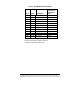
Table 2. DCE MASTER PORT CHART Signal Direction of DCE Master Port Pin # Signal Description 2 TD Transmit Data Input 3 RD Receive Data Output 4 RTS Request to Send Input 5 CTS Clear to Send Output 6* DSR Data Set Ready Output 7 SG Signal Ground <------> 8* CD Carrier Detect Output 20 DTR Data Term. Ready Input 14** TD (B) Transmit + Output 15** TD (A) Transmit Output 16** RD (B) Receive + Input 17** RD (A) Receive Input * Pins 6 & 8 are tied together inside the 232D4SS8 and share the same output.
Table 3. DTE MASTER PORT CHART Pin # 2 3 4 5 Signal TD RD RTS CTS Description Transmit Data Receive Data Request to Send Clear to Send Signal Direction of DTE Master Port Output Input Output Input 6* DSR Data Set Ready Input 7 SG Signal Ground <------> 8* CD Carrier Detect Input 20 DTR Data Term. Ready Output 14** TD (B) Transmit + Output 15** TD (A) Transmit Output 16** RD (B) Receive + Input 17** RD (A) Receive Input * Pins 6 & 8 are tied together inside the 232D4SS8 and share the same input.
Table 4. DTE PORTS A - H RS-232 Signal Direction of DTE Ports A Pin # Signal Description through H 2 TD Transmit Data Output 3 RD Receive Data Input 4 RTS Request to Send Output 5 CTS Clear to Send Input 6* DSR Data Set Ready Input 7 SG Signal Ground <------> 8* CD Carrier Detect Input 20 DTR Data Term Ready Output 14** TD(B) Transmit (+) Output 15** TD(A) Transmit (-) Output 16** RD(B) Receive (+) Input 17** RD(A) Receive (-) Input *Pins 6 & 8 are tied together inside the 232D4SS8 and share the same input.
Figure 5. Simplified RS-232 Schematic RS-422/485 Slave Port Option The RS-232 transmit and receive data signals on the Master port will be converted to balanced, full-duplex RS-422 or half-duplex RS-485 signals with this option. The 232D4SS8 comes standard with four RS-485 (2 or 4-wire) slave ports. Refer to Appendix B for cable charts. Table 5.
Figure 6. Simplified RS-422/485 Schematic When a port has this option, additional circuitry will be mounted to the main board. The standard 232D4SS8 comes with the RS-485 option on four ports (Port A-D). Use Figure 2 to locate its position. Refer to Table 5 for pin-out, signal name, and signal direction information. Also, refer to Figure 6 for a simplified schematic showing the relationship between the Master port and a port configured with the RS-422/485 option.
There are two components located in the port B circuit area on the main printed circuit board, a resistor (R75) and a capacitor (C4), that are part of the send data control circuit. These components are factory selected for 9600 baud, which allows the send data control to operate at 9600 baud or higher. With these two components the RS-485 driver will be disabled approximately 1 millisecond after the last character has been sent.
Another option available on the 232D4SS8 is the slave ports set up as RS-422 ports. This means that the driver and receiver will be enabled all the time. RS-422 allows point-to-point operation or up to 10 receive only units up to 4000 feet on two pair of lines. Smart Switch Operation The 232D4SS8 has two modes in which it can select ports, smart switch, and smart switch/port combiner. Smart Switch Mode Position 6 of SW1 must be in the off position to enable this mode. Refer to Figure 2 and Table 1.
To turn any selected port off, the first and second character of the command control string must be the user-defined character. The third character must be the ASCII EOT character (decimal 4). Example 2: To turn off all ports, with ASCII STX (decimal 2) set as the user defined character. Send to the Master Port: STX STX EOT (2 2 4 decimal) It is recommended that the user-defined character be a nonprintable character.
The turn off string also adds the ASCII ESC character to the front of the three-character turn off string. The first character is the ASCII ESC character. The second and third character of the command control string is the user-defined character. The fourth character is the ASCII EOT character (decimal 4). Example 2: To turn off all ports and the user defined character is ASCII STX (decimal 2).
Table 4. SW2 Weight Chart DIP Switch 2 1 2 3 4 5 6 7 8 Weight 1 2 4 8 16 32 64 128 For example, if you wish to use the ASCII NAK character as the user defined character, which has a decimal value of 21, you would turn on switches 1, 3, and 5 (1 + 4 + 16 = 21).
soon as the CTS line on port A was lowered. At that time any of the other RS-232 ports on the 232D4SS8 can raise their CTS line to establish connection. If port A is connected to the Master port and any of the other RS-232 ports on the 232D4SS8 raises their CTS line, the data sent to the 232D4SS8 from those ports would be lost. The 232D4SS8 does not have buffering.
Chapter 2: SOFTWARE 232D4SS8 Users Any references to the 232XSS in this section are also intended for the 232D4SS8 Smart Switch. Introduction The 232D4SS8 is shipped with 2 disks containing a Windows software program that will test the operation of the Smart Switch. When installed the program will allow the Smart Switch to select all available ports.
Method Two • Place the “Windows” disk #1 in drive A. (The instruction use drive A as default for the floppy drive. Replace A with your drive letter if necessary) • Select Programs from the Start Button and click on Windows Explorer. Click on the drive containing the SS Setup Disk. • Double click on the file “Setup.exe”. • Follow the instructions of the setup program. Smart Switch Setup To open the program select the Start button then Programs.
Selecting Ports To change the com port the user need only go to the Settings Menu and select the Com Port tab. Then select the com port to which the device is attached. The Smart Switch program supports com ports 1 through 6.
APPENDIX A: ASCII Character Codes DECIMAL to HEX to ASCII CONVERSION TABLE DEC HEX ASCII KEY DEC HEX ASCII DEC HEX ASCII DEC HEX ASCII 0 0 NUL ctrl @ 32 20 SP 64 40 @ 96 60 ` 1 1 SOH ctrl A 33 2 2 STX ctrl B 34 21 ! 65 41 A 97 61 a 22 “ 66 42 B 98 62 3 3 ETX ctrl C b 35 23 # 67 43 C 99 63 4 4 EOT c ctrl D 36 24 $ 68 44 D 100 64 d 5 5 6 6 ENQ ctrl E 37 25 % 69 45 E 101 65 e ACK ctrl F 38 26 & 70 46 F 102 66 7 f 7 BE
APPENDIX B: Cable Charts These charts indicate some common cable wiring based on the DCE/DTE configuration of the Master Port. Refer to the Port Configuration section of this manual for information on Master Port configurations. Chart 1. IBM PC DB25 Connector to Master Port Master port configured as a DCE port.
Chart 3. Modem DB25 Connector to Master Port Master port configured as a DTE port. 232D4SS8 Async Modem Master Port (DTE) Serial Port Signal DB25 Connector DB25 Connector Direction 2 <----------2 3 -----------> 3 4 <----------4 5 -----------> 5 7 <---------> 7 8 -----------> 8* 20 <----------20 * Pins 6 & 8 are tied together inside the 232D4SS8 and share the same input. NOTE: When using chart 3 above and connecting a DTE device to ports A - H of the smart switch, refer to Charts 7 and 8. Chart 4.
Chart 5. IBM PC DB25 Connector to Ports A - H (DTE) Master port configured as a DCE port. 232D4SS8 IBM PC Ports A - H (DTE) Serial Port Signal DB25 Connector DB25 Connector Direction 2 -----------> 3 3 <----------2 4 -----------> 5 5 <---------4 6 <---------6* 7 <---------> 7 8 <----------8* 20 -----------> 20 * Pins are tied together inside the 232D4SS8 and share the same input. Chart 6. IBM PC DB9 Connector to Ports A - H (DTE) Master port configured as a DCE port.
Chart 7. IBM PC DB25 Connector to Ports A - H (DTE) Master port configured as a DTE port with a modem connected (see Chart 3). 232D4SS8 IBM PC Ports A - H (DTE) Serial Port Signal DB25 Connector DB25 Connector Direction 2 -----------> 3 3 <----------2 4 -----------> 5 5 <----------4 6 <---- ----> 6* 7 <---------> 7 8 <----------20 20 -----------> 6* * Pins 6 & 8 are tied together inside the 232D4SS8 and share the same input. Chart 8.
Chart 9. RS-422/485 4-Wire Device to Port (A - H) Configured as an RS-422 /485 Port. 232D4SS8 RS-422/485 Ports A - H 4-Wire Signal DB25 Connector Device Direction TD (A)* -----------> 17 - RD (A) TD (B)* -----------> 16 - RD (B) Signal Ground <----------> 7 - SG RD (A)* <----------15 - TD (A) RD (B)* <----------14 - TD (B) * If the device being connected uses "+" and "-" in place of "B" and "A", the "+" replaces the "B" and the "-" replaces the "A".
APPENDIX C: Declaration of Conformity DECLARATION OF CONFORMITY Manufacturer’s Name: Manufacturer’s Address: Model Number: Description: Type: Application of Council Directive: Standards: B&B Electronics Manufacturing Company P.O. Box 1040 707 Dayton Road Ottawa, IL 61350 USA 232D4SS8 Eight-port Smart Switch Light industrial ITE equipment 89/336/EEC EN 50082-1 EN 61000 (-4-2, -4-3, -4-4, -4-6) William H.