
Instruction Manual


5
2
ABOUT LINK INTEGRITY
During normal operation, link integrity pulses are transmitted by all
point-to-point Ethernet devices. When an iMcV-Giga-MediaLinX receives
valid link pulses, it knows that the device to which it is connected is up and
sending pulses, and that the copper or fiber cable coming from that device
is intact. The appropriate “LNK” (link) LED is lit to indicate this.
The iMcV-Giga-MediaLinX also sends out link pulses from its copper and
fiber transmitters, but normally has no way of knowing whether the cable
to the other device is intact and the link pulses are reaching the other end.
The combination of FiberAlert and LinkLoss allows this information to be
obtained, even when physical access to a remote device (and its link integri-
ty LED) is not available.
WHAT I
S TX LINKLOSS?
TX LinkLoss is a troubleshooting feature. When a fault occurs on the
twisted pair segment of a conversion, TX LinkLoss detects the fault and
passes this information to the fiber segment. If a media converter is not
receiving a twisted pair link, TX LinkLoss disables the transmitter on the
media converter's fiber port. This results in a loss of link on the device con-
nected to the fiber port.
Enable TX LinkLoss by setting DIP Switch 5 to the ON position.
W
HAT IS
FIBERALERT?
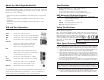
FiberAlert is a troubleshooting feature that minimizes the problems asso-
ciated with the loss of one strand of fiber. If a strand is unavailable, the
device at the receiver end notes the lost
link. The device will then stop transmit-
ting data and the link signal until a signal
or link pulse is received. The result is
that the link LED on BOTH sides of the
fiber connection will go out indicating a
fault somewhere in the fiber loop. Using
FiberAlert, a local site administrator is
notified of a fault and can quickly deter-
mine where a cable fault is located.
Enable FiberAlert by setting DIP Switch 6 to the ON position.
U
SING FIBERALERT AND LINKLOSS
For a typical Main Site to Remote Site conversion, the iMcV-Giga-
MediaLinX should be enabled as follows:
• Enable TX LinkLoss at the Main Site
• Enable FiberAlert at the Remote Site
Installing the iMcV-Giga-MediaLinX
The iMcV-Giga-MediaLinX installs in any IMC Networks chassis, each
requiring one slot.
To install a module, remove the blank brackets covering the slots where
the module is to be installed (if present) by removing the screws on the out-
side edges of the bracket. Slide the module into the chassis, via the card
guides, until the module is seated securely in the connector. Secure the
module to the chassis by tightening the captive screw. Save any “blanks”
removed during installation for future use should the configuration require-
ments change.
INSTALLATION
TROUBLESHOOTING
• During installation, test the fiber and twisted pair connections with all
troubleshooting features disabled, then enable these features, if desired,
just before installation. This will reduce the features’ interference with
testing.
• Any testing of the module should be performed in an unmanaged envi-
ronment. Either test in an unmanaged chassis or disable management in
a managed chassis, where possible.
• LNK LEDs will only function after BOTH twisted pair and fiber connec-
tions have been established.
• If using a high powered device (for long distance installations) for a short
distance installation, the fiber transmitters may overdrive the receivers
and cause data loss. In such a case, add an optical attenuator to the
connection.
Configuring the iMcV-Giga-MediaLinX
The iMcV-Giga-MediaLinX may be configured with various features such
as LinkLoss, FiberAlert, Auto-Negotiation, duplex mode and speed. The fol-
lowing sections include instructions for configuring both managed (via an
SNMP-compatible management application like iView²) and unmanaged
modules.
MANAGED MODULES
To manage an iMcV-Giga-MediaLinX, it must be installed within an
SNMP-Manageable chassis. In a managed environment, install the module
first, then configure using the management software. Within iView², con-
figure features and troubleshooting functions in the Module Detail section
under the picture of the module. See the iView² online help file for more
information.
NOTE
Until a module installed in a managed chassis is configured via the software, the
module (and its LEDs) may not work properly.
NOTE
Enable FiberAlert on ONE side of a media conversion only; Enabling it on
both sides would keep both transmitters off indefinitely.