PC Watchdog Timer Card CE Models: ATRWDT and ATXWDT Documentation Number ATxWDT-1303 This product designed and manufactured in Ottawa, Illinois USA of domestic and imported parts by International Headquarters B&B Electronics Mfg. Co. Inc. 707 Dayton Road -- P.O. Box 1040 -- Ottawa, IL 61350 USA Phone (815) 433-5100 -- General Fax (815) 433-5105 Home Page: www.bb-elec.com Sales e-mail: orders@bb-elec.com -- Fax (815) 433-5109 Technical Support e-mail: support@bb.elec.
Table of Contents CHAPTER 1: GENERAL INFORMATION...................................1 INTRODUCTION ..................................................................................1 FEATURES..........................................................................................1 SPECIFICATIONS ................................................................................1 CHAPTER 2: SETUP AND INSTALLATION...............................2 INSPECTION ........................................................
Chapter 1: GENERAL INFORMATION Introduction B&B Electronics' Watchdog Timer (WDT) Cards, Models ATRWDT and ATXWDT, are hardware devices designed to overcome the dangers or annoyances associated with a PC "locking up." Your software periodically resets the WDT. If the watchdog doesn't receive the reset trigger within a software selectable timeout period, the WDT resets the computer.
Chapter 2: SETUP AND INSTALLATION Inspection Your WDT has been tested for proper operation. It should be in perfect electrical and mechanical condition upon receipt. Remove the card from its protective packaging. Handle the card only by its edges being careful not to touch the gold connection fingers. Save the packaging for storage or shipping if the card needs repair.
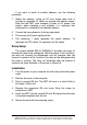
Figure 1. ATRWDT/ATXWDT PCB Silk Screen Documentation Number ATxWDT-1303 B&B Electronics Mfg Co – 707 Dayton Rd - PO Box 1040 - Ottawa IL 61350 - Ph 815-433-5100 - Fax 815-433-5104 B&B Electronics Ltd – Westlink Comm.
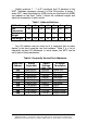
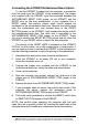
Switch positions 1 - 7 of S1 configure the I/O address of the WDT. Switches represent a binary 0 in the ON position, a binary 1 when OFF. Least significant bit (LSB) and most significant bit (MSB) are labeled on the card. Table 1 shows the numerical weight and electrical connection of each switch. Table 1.
If you want to install at another address, use the following procedure. 1. Select the address: Using an I/O port usage table (one is included in Appendix A) select an unused hex address space. Note that the WDT card occupies 8 bytes of I/O space. Use caution when selecting a port address, it is important that nothing else is installed at the selected address. 2. Convert the hex address to its binary equivalent. 3. Throw away the 3 least significant bits. 4.
Connecting the ATRWDT Motherboard Reset Option To use the ATRWDT to reboot the host computer, a connection must be made from the ATRWDT to the motherboard. The jumper wire supplied with the ATRWDT must be connected between the MOTHEBOARD RESET PINS jumper on the ATRWDT and the RESET pins on the host motherboard. If your computer has a RESET switch, the switch's jumper wires should already be connected to the motherboard reset pins.
Connecting the ATX Reset Option for the ATXWDT The ATXWDT uses the ATX Power supply to reset the computer. The ATXWDT sends a 5 volt, 10 second signal on the PS-ON data line to turn off the computer for 10 seconds. Then when this signal goes back to zero the computer turns back on. The ATX daughter board also allows the computer to bypass the ON/OFF button. Setting the jumper to ON/OFF will allow the ON/OFF button to work as normal.
contains a historic description of the product. The file, READ.ME, contains corrections and additions to the printed user’s manual. 8 Documentation Number ATxWDT-1303 B&B Electronics Mfg Co – 707 Dayton Rd - PO Box 1040 - Ottawa IL 61350 - Ph 815-433-5100 - Fax 815-433-5104 B&B Electronics Ltd – Westlink Comm.
Chapter 3: OPERATION Communicating with the WDT The WDT uses a four-bit latch to start and stop the timers and set the timeout period. Regardless of the mode of operation of the WDT, a "1" must be written to the least significant bit of the latch to start the timers. Writing a "0" to the least significant bit of the latch at any time will stop the timers.
The four bit latch values are also readable. Reading these bits is recommended to verify the presence and setup of the WDT. The BASIC command INP is used to read from the WDT. The top three bits are not used and can be masked out. In the ATRWDT the fifth bit is the reset flag. It will be a 1 when the ATRWDT resets the computer and a 0 if the computer has not been reset by the ATRWDT. This bit will be cleared if the computer is turned off or after the bit has been read.
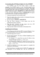
Figure 2. Output Schematic Documentation Number ATxWDT-1303 B&B Electronics Mfg Co – 707 Dayton Rd - PO Box 1040 - Ottawa IL 61350 - Ph 815-433-5100 - Fax 815-433-5104 B&B Electronics Ltd – Westlink Comm.
Chapter 4: SOFTWARE The software shipped with the ATRWDT and ATXWDT includes example software for Windows 3.11, Windows 95 and Windows NT written for Borland C++ 5.01, Microsoft Visual C++ 4.0 and Microsoft Visual BASIC 4.0. Also included is a Windows NT 4.0 device driver. Windows NT and Windows 95 Windows NT restricts access to the I/O ports of the computer to device drivers, so a simple OUT command cannot be used to communicate with the watchdog timer. A device driver, for use with Windows NT 4.
Changing the I/O Port Address The setup program, WDTSETUP.EXE, changes the I/O port address that the software uses to communicate with watchdog timer. This address must match the setting of the jumper switches on the watchdog timer. The program updates keys in the registry for the device driver. In order to update these keys under Windows NT Server, the user must be logged in as the administrator or have administrator rights. Windows NT Workstation and Windows 95 allow all users to modify these keys.
In Borland C++, a program using the watchdog timer must include PCWDT.H and PCWDT16.LIB in the project to use the watchdog timer commands. The example program uses Borland’s EasyWin to demonstrate the use of the DLL functions. A Borland C++ project file is included to make it easier to recompile the example program. Changing the I/O Port Address The I/O port address that the software uses to communicate with the watchdog timer is stored in the file, PCWDT.INI, located in the Windows directory.
Command Reference BBPCWDT_Startup Purpose: Begin communications with the watchdog timer. C Syntax: HANDLE BBPCWDT_Startup(void); BASIC Syntax: Function BBPCWDTStartup () As Long Remarks: This function reads the watchdog timer’s I/O port value that the setup program stored in the registry for Windows 95 / NT or in the file, PCWDT.INI, for Windows 3.11. The Windows NT version of this function establishes communications with the PCWDT device driver. The Windows 3.
BBPCWDT_Reset Purpose: Reset the timeout of the watchdog timer. C Syntax: BOOL BBPCWDT_Reset(HANDLE hDev, BYTE bResetValue); BASIC Syntax: Function BBPCWDTReset (ByVal hDev As Long, ByVal bResetValue As Byte) As Byte Remarks: hDev is the handle to the watchdog timer that was returned by BBPCWDT_Startup. bResetValue is the reset value that is sent to the watchdog timer. The values are: Return Value: Value (hex) Timeout 0 disabled 1 0.
BBPCWDT_ReadRegister Purpose: Read the value of the reset register. C Syntax: BOOL BBPCWDT_ReadRegister(HANDLE hDev, BYTE* value); BASIC Syntax: Function BBPCWDTShutdown (ByVal hDev As Long, value As Byte) As Byte Remarks: hDev is the handle to the watchdog timer that was returned by BBPCWDT_Startup. value is a pointer to a byte that will receive the register value. Return Value: TRUE (non-zero) if successful, otherwise FALSE (zero).
Appendix A: Hardware I/O Maps I/O Map of XT Class Machines Hex Address 000-00F 020-021 040-043 060-063 080-083 0A0-0AF 200-20F 210-217 2E8-2EF 2F8-2FF 300-31F 320-32F 378-37F 380-38F 3B0-3BF 3D0-3D7 3E8-3EF 3F0-3F7 3F8-3FF Address Function in XT Class Machines DMA controller (8237A) Interrupt controller (8259A) timer (8253) PPI(8255A) DMA page register (74LS612) NMI – non maskable interrupt game port joystick controller Expansion unit COM4 serial port COM2 serial port Prototype card hard disk Parallel prin
I/O Map of AT Class Machines Hex Address Address Function in AT Class Machine 000-01F DMA controller #1 (8237A-5) 020-03F Interrupt controller #1 (8259A) 040-05F timer (8254) 060-06F Keyboard (8042) 070-07F NMI – non maskable interrupt & CMOS RAM 080-09F DMA page register (74LS612) 0A0-0BF Interrupt controller #2 (8259A) 0C0-0DF DMA controller #2 (8237A) 0F0-0FF 80287 math coprocessor 1F0-1F8 hard disk 200-20F game port joystick controller 258-25F Intel Above Board 278-27F parallel printer port 2 2E8-2EF CO
Appendix B: QuickBASIC Example Note: An additional test program for the WDT is available on B&B’s ftp site at ftp.bb-elec.com/bb-elec/software. B&B Electronics Mfg. Co. Watchdog Timer QuickBASIC Example Program This code is an example of how the WDT is addressed from within a program. This code would be used when the TIMER RESET INPUT jumper is in the "CODE" position.
Appendix C: Declaration of Conformity Statement DECLARATION OF CONFORMITY Manufacturer’s Name: Manufacturer’s Address: B&B Electronics Manufacturing Company P.O. Box 1040 707 Dayton Road Ottawa, IL 61350 USA Model Numbers: ATRWDT, ATXWDT Description: PC ISA Watchdog Card Type: Light industrial ITE equipment Application of Council Directive: 89/336/EEC Standards: EN55022 EN50082-1: EN61000 (-4-2, -4-3, -4-4, -4-6) William H.