
Switch User Manual


Documentation Number 232BSS42907 Manual Appendix B: Cable Charts B-1
B&B Electronics Mfg Co Inc – 707 Dayton Rd - PO Box 1040 - Ottawa IL 61350 - Ph 815-433-5100 - Fax 815-433-5104
B&B Electronics Ltd – Westlink Commercial Park – Oranmore, Galway, Ireland – Ph +353 91-792444 – Fax +353 91-792445
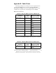
Appendix B: Cable Charts
All charts give full pin outs. Only pins 2 & 3 are required for basic
operation. Handshaking pins are needed for hardware (RTS/CTS)
handshaking or if DTR is to be used to signal the Master port to accept
commands. See Appendix C for a block diagram of the 232BSS4.
Master Port Connections:
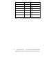
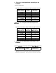
Chart B.1. DTE (PC) DB25 Connector to Master Port
DTE (PC)
Serial Port
DB25 Connector
Signal
Direction
232BSS4
Master Port (DCE)
DB25 Connector
2 -----------> 2
(TD)
3 <----------- 3
(RD)
4 -----------> 4
(RTS)
5 <----------- 5
(CTS)
6 <----------- 6
(DSR) *
7 <---------> 7
(GND)
8 <----------- 8
(DCD) *
20 -----------> 20
(DTR) *
* - Pins 6, 8, & 20 looped back internally on the 232BSS4
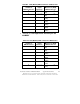
Chart B.2. DTE (PC) DB9 Connector to Master Port
DTE (PC)
Serial Port
DB9 Connector
Signal
Direction
232BSS4
Master Port (DCE)
DB25 Connector
1 <----------- 8
(DCD) *