UNO-2170 Celeron M Universal Network Controller with PC/104 extension User Manual
Copyright This document is copyrighted, © 2004. All rights are reserved. The original manufacturer reserves the right to make improvements to the products described in this manual at any time without notice. No part of this manual may be reproduced, copied, translated or transmitted in any form or by any means without the prior written permission of the original manufacturer. Information provided in this manual is intended to be accurate and reliable.
Product Warranty Advantech warrants to you, the original purchaser, that each of its products will be free from defects in materials and workmanship for one year from the date of purchase. This warranty does not apply to any products that have been repaired or altered by persons other than repair personnel authorized by Advantech, or which have been subject to misuse, abuse, accident or improper installation. Advantech assumes no liability under the terms of this warranty as a consequence of such events.
UNO-2170 User Manual iv
Contents Chapter 1 Overview ...........................................................2 1.1 1.2 1.3 1.4 Introduction ....................................................................... 2 Hardware Specifications ................................................... 3 Safety Precautions ............................................................. 4 Chassis Dimensions........................................................... 5 Figure 1.1:Chassis Dimensions.......................................
Figure 3.1:Chassis Grounding Connection ................... 18 3.3 3.4 3.5 Connecting Power ........................................................... 19 Installing a Hard Disk ..................................................... 19 BIOS Setup and System Assignments ............................ 19 Appendix A System Settings and Pin Assignments ..........22 A.1 System I/O Address and Interrupt Assignment............ 22 A.2 Board Connectors and Jumpers.......................................
1 2 Overview This chapter provides an overview of UNO-2170s specifications.
Chapter 1 Overview 1.1 Introduction UNO-2170 is an embedded Application Ready Platform (ARP) that can shorten your development time and offers rich networking interfaces to fulfill extensive needs in different projects. Advantech Universal Network Controller is designed to be a total solution for network enabled Application Ready Platforms. Leveraging field-approved and worldwide approved real-time OS technology, Advantech UNO-2000 series provides a Windows CE .
1.2 Hardware Specifications CPU: Up to Celeron-M 1GHz Ultra low-voltage version Memory: 256/512 MB DDR on board (Default: 256 MB DDR). Battery-backup RAM: 512 KB Battery-backup RAM VGA/Keyboard/Mouse: DB-15 VGA Connector, PS/2 keyboard and mouse Serial Ports: 2 x RS-232 and 2 x RS-232/422/485 with DB-9 connectors. Automatic RS-485 data flow control Serial Speeds: RS-232: 50~115.2 kbps, RS-422/485: 50~921.6 kbps LAN: Two 10/100 Base-T RJ-45 Ports USB interface: Two USB ports, USB UHCI, Rev. 1.
1.3 Safety Precautions The following sections tell how to make each connection. In most cases, you will simply need to connect a standard cable. Warning! Always disconnect the power cord from your chassis whenever you are working on it. Do not connect while the power is on. A sudden rush of power can damage sensitive electronic components. Only experienced electronics personnel should open the chassis. Caution! Always ground yourself to remove any static electric charge before touching UNO-2170.
1.4 Chassis Dimensions Figure 1.
UNO-2170 User Manual 6
2 2 Hardware Functionality This chapter shows how to setup the UNO-2170s hardware functions, including connecting peripherals, setting switches and indicators.
Chapter 2 Hardware Functionality 2.1 Introduction The following two figures show the connectors on UNO-2170. The following sections give you detailed information about function of each peripheral. Figure 2.1: Front panel of UNO-2170 Figure 2.2: Rear panel of UNO-2170 2.2 RS-232 Interface (COM1~COM2) The UNO-2170 offers two standard RS-232 serial communication interface ports: COM1 and COM2. Please refer to A.3 for their pin assignments.
2.3 RS-232/422/485 Interface (COM3~COM4) The UNO-2170 offers two RS-232/422/485 serial communication interface ports: COM3 and COM4. Please refer to Appendix A.4 for their pin assignments. The default setting of COM3 and COM4 are RS-422/485. 2.3.1 16C550 UARTs with 16-byte standard Advantech UNO-2170 comes with TI16C550 UARTs containing 16 bytes FIFOs. 2.3.2 RS-422/485 detection In RS-422/485 mode, UNO-2170 automatically detects signals to match RS-422 or RS-485 networks. (No jumper change required) 2.3.
2.3.5 RS-232/422/485 Selection COM3 and COM4 support 9-wire RS-232, RS-422 and RS-485 inter faces. The system detects RS-422 or RS-485 signals automatically in RS422/485 mode. To select between RS-422/485 and RS-232 for COM3, adjust JP4. To select between RS-422/485 and RS-232 for COM4, adjust JP5. Jumper setting for RS-422/485 interface: (Default setting). (JP4 and JP5) Figure 2.3: RS-422/485 jumper setting Jumper setting for RS-232 interface: (JP4 and JP5) Figure 2.
2.3.6 RS-485 Auto Flow Control Mode and RS-422 Master/Slave Mode Selection You can set the “Auto Flow Control mode of RS-485 or “Master/Slave" mode of RS-422 by using the SW3 DIP switch for each RS-422/485 port. In RS-485, if the switch is set to “Auto" the driver automatically senses the direction of the data flow and switches the direction of transmission. No handshaking is necessary. In RS-422, if DIP switch is set to “On", the driver is always enabled, and always in high or low status.
2.3.7 IRQ and Address Setting The IRQ and I/O address range of COM3 and COM4 are listed below: COM3: 3E8H, IRQ10 (Independent IRQ), IRQ10 (Share IRQ) COM4: 2E8H, IRQ5 (Independent IRQ), IRQ10 (Share IRQ) Vector address for share IRQ: 1D0H You can set “Share IRQ" or “Independent IRQ" by the first switch of SW4. Table 2.2: IRQ Setting via switch 1 at SW4 Switch 1 at SW4 setting Function Shared IRQ (Default) Independent IRQ You can adjust the transmission rate by the second switch of SW2. Table 2.
2.4 LAN: Ethernet Connector The UNO-2170 is equipped with a Realtek RTL8139C Ethernet LAN controller that is fully compliant with IEEE 802.3u 10/100Base-T CSMA/CD standards. The Ethernet port provides a standard RJ-45 jack on board, and LED indicators on the front side to show its Link (Green LED) and Active (Yellow LED) status. 2.5 Power Connector The UNO-2170 comes with a Phoenix connector that carries 9~36 VDC external power input, and features reversed wiring protection.
2.8 PCMCIA: PC Card Slot The UNO-2170 provides one PC Card slot that supports CardBus (Card32) cards and 16-bit (PCMCIA 2.1/JEIDA 4.2) card standards. It supports +3.3 V, +5 V and +12 V @ 120 mA working voltage. The PC Card is 85.6 mm long by 54 mm wide (3.37" x 2.126"), use a 68-pin connector and a removable module standardized by PCMCIA that is known as “PCMCIA card". PS: PCMCIA interrupt assignment is IRQ 9. 2.
2.10 Battery Backup SRAM UNO-2170 provides 512 KB of battery backed SRAM. This ensures that you have a safe place to store critical data. You can now write software applications without being concerned that system crashes will erase critical data from the memory. There is a BTRY LED in the front panel of the UNO-2170, please replace the lithium battery with a new one if the BTRY LED is activated. 2.10.
UNO-2170 User Manual 16
3 2 Initial Setup This chapter introduces how to initialize the UNO-2170.
Chapter 3 Initial Setup 3.1 Inserting a CompactFlash Card The procedure for installing a CompactFlash™ card into the UNO-2170 is detailed below, please follow these steps carefully. 1. Remove the power cord. 2. Unscrew the four screws from the rear panel of the UNO-2170. 3. Remove the rear panel. 4. Plug a CompactFlash™ card with your OS and application program into a CompactFlash™ card slot on board. 5. Screw back the rear panel with four screws.
You can select if you wish to combine the chassis grounding point with the system grounding by using an onboard jumper selection. (JP7) Open - Separates system power ground and chassis ground. (default) Closed - Connects system power ground and chassis ground. 3.3 Connecting Power Connect the UNO-2170 to a 9~36 VDC power source. The power source can either be from a power adapter or an in-house power source. 3.4 Installing a Hard Disk The procedure for installing a hard disk into the UNO-2170 is below.
UNO-2170 User Manual 20
A System Settings and Pin Assignments
Appendix A System Settings and Pin Assignments A.1 System I/O Address and Interrupt Assignment Table A.
Table A.1: UNO-2170 System I/O Ports Address Range Device 3D0-3DF Color/graphics monitor adapter 3F0-3F7 Diskette controller 3E8-3EF Serial port 3 3F8-3FF Serial port 1 443 Watchdog timer DC000-DFFFF Battery backup resource Table A.2: UNO-2170 Interrupt Assignment Interrupt No.
A.2 Board Connectors and Jumpers There are several connectors and jumpers on the UNO-2170 board. The following sections tell you how to configure the UNO-2170 hardware setting. Figure A-1 and Figure A-2 show the locations of UNO-2170’s connectors and jumpers. Figure A.1: UNO-2170 connector and jumper locations (front-side) Figure A.
Table A.
A.3 RS-232 Standard Serial Port (COM1~COM2) Table A.
A.4 RS-232/422/485 Serial Port (COM3~COM4) Table A.5: RS-232/422/485 serial port pin assignments Pin RS-232 RS-422 RS-485 1 DCD Tx- DATA- 2 RxD Tx+ DATA+ 3 TxD Rx+ NC 4 DTR Rx- NC 5 GND GND GND 6 DSR NC NC 7 RTS NC NC 8 CTS NC NC 9 RI NC NC A.5 Ethernet RJ-45 Connector (LAN1~LAN2) Table A.
A.6 Phoenix Power Connector (PWR) Table A.7: Power connector pin assignments Pin 10/100Base-T Signal Name 1 +9~36VDC 2 GND A.7 PS/2 Keyboard and Mouse Connector Table A.
A.8 USB Connector (USB1~USB2) Table A.9: USB connector pin assignments Pin Signal Name Cable Color 1 VCC Red 2 DATA+ White 3 DATA- Green 4 GND Black A.9 VGA Display Connector Table A.
UNO-2170 User Manual 30
B Programming the Watchdog Timer
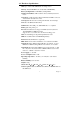
Appendix B Programming the Watchdog Timer Bellow is a sample of programming code for controlling the Watchdog Timer function.
33 Appendix B
UNO-2170 User Manual 34