Bioscrypt Inc. Architect & Engineer Specification V-Smart™ Fingerprint Reader May 2, 2006 1. Introduction The intent of this document is to describe the specifications, operation, and physical attributes of the V-Smart fingerprint reader, Model Number V-SMART, A, manufactured by Bioscrypt, Inc. The device specifications, installation specifications, and connections are provided in detail for system architects and engineers designing access control and other systems utilizing the V-Smart reader. 2.
Page 2 The “finger mask” that surrounds the fingerprint sensor itself shall be a carbon fiber conductive plastic. 3.3. Fingerprint Sensor The V-Smart reader shall incorporate the Authentec, Inc. sensor model AF-S2. The AF-S2 sensor shall be manufactured of silicon and shall be capacitivebased. The sensor surface area shall measure 24 x 24 x 3.5 mm.
Page 3 The two V-Smart modules (fingerprint verification and smart card interface) must be connected behind the wall plate. Once the cables are connected, the wall plate may be mounted to the wall. The V-Smart modules shall have two tabs that slide into slots on the wall plate. Each module shall be secured to the wall plate by a single #4-40 inch screw. 3.7.
Page 4 Figure 1: V-Smart Wall Mounting Plate 4. Certifications and Approvals The V-Smart has been tested for compliance with all applicable international standards and shall have the following approvals: FCC, UL294, CSA, cUL, CE under R&TTE. These approvals shall be printed on the labeling located on the rear panel of the reader. 4.1. Frequency The V-Smart shall include an embedded Gemplus GemEasyLink680SL MIFARE contactless smart card reader.
Page 5 Operating Frequency Range: RF Power Rating: RF Output Impedance: 13.553 – 13.567 MHz 0.0 Watts 50 Ohms 4.2. FCC Information to Users The V-Smart shall comply with the limits for a Class A digital device, pursuant to Part 15 of the FCC Rules. These limits are designed to provide reasonable protection against harmful interference when the equipment is operated in a commercial environment.
Page 6 Pass-Thru Filter: Manufacturer: Spectrum Control Fairview, Pennsylvania USA, 16415 http://www.SpectrumControl.com 56-605-019 Part Number: NOTE: The installation of these filters is mandatory for the registered CE mark, and associated R&TTE directive compliance to be valid within the European Union. Failure to do so will render the CE mark and consequent right to operate the equipment null and void.
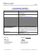
Page 7 DECLARATION OF CONFORMITY FOR THE R&TTE DIRECTIVE 1999/5/EC Manufacturer’s Name/Address: Address: Contact Person: Equipment Type: Product Name: Model No.: RF Output Power: Transmitter Operating Frequency Range: Emission Designation: Duty Cycle: Year of manufacture: Country Of Manufacture: The above product has been tested by UltraTech Engineering Labs Inc., and found to comply with: Test Laboratories: Bioscrypt Inc. 5450 Explorer Drive, Suite 500 Mississauga, Ontario Canada, L4W 5M1 Mr.
Page 8 DECLARATION OF CONFORMITY FOR THE EMC DIRECTIVE 89/336/EEC Manufacturer’s Name/Address: Address: Contact Person: Equipment Type: Product Name: Model No.: RF Output Power: Transmitter Operating Frequency Range: Emission Designation: Duty Cycle: Year of manufacture: Country Of Manufacture: The above product has been tested by UltraTech Engineering Labs Inc., and found to comply with: Test Laboratories: Bioscrypt Inc. 5450 Explorer Drive, Suite 500 Mississauga, Ontario Canada, L4W 5M1 Mr.
Page 9 DECLARATION OF CONFORMITY FOR THE LOW VOLTAGE SAFETY DIRECTIVE 73/23/EEC Manufacturer’s Name/Address: Address: Contact Person: Equipment Type: Product Name: Model No.: RF Output Power: Transmitter Operating Frequency Range: Emission Designation: Duty Cycle: Year of manufacture: Country Of Manufacture: The above product has been tested by UltraTech Engineering Labs Inc., and found to comply with: Test Laboratories: Bioscrypt Inc.
Page 10 5. Environmental Specifications The V-Smart shall be manufactured for indoor use, and if placed outdoors must be installed within a complete Bioscrypt certified enclosure to protect the reader against direct contact with the elements, including rain, sun, snow, or excessive moisture. Failure to place V-Smart readers installed outdoors within such an enclosure will void the warranty. 5.1.
Page 11 cable shall be provided with each V-Smart reader to facilitate connecting the reader to other wiring. The remainder of this document assumes you are using the pigtail cable provided to make connections. Appendix A: Pigtail Cable Connections lists the connections available through the pigtail. Also, see Section 7: Communications and Section 8: Connections to External Equipment.
Page 12 recommended). Pin 11 should be connected to Power GND and Pin 13 should be connected to +12 VDC power input. 6.3. Grounding The V-Smart reader shall have various grounding requirements: Power GND (Pin 11): the return for the input power supply. Pin 11 shall be connected to the negative on the power supply. Refer to Section 6.2: Power Requirements for further details. Wiegand GND (Pin 6): the reference ground for the Wiegand Data 0 and Data 1 interface.
Page 13 Only two of the three ports may be activated at a time. By default, the V-Smart shall be configured for Port Mode 0 (Host RS-232 DB15 / Aux RS-232 RJ11) because Host RS-232 protocol is necessary for communications between the smart card interface and fingerprint verification modules. Thus, the RS-232 DB15 port may NOT be used for PC communications.
Page 14 Use Category 5 rated cable (shielded is recommended). This cable should be dedicated to the RS-485 network connection between the B&B Electronics 485TBLED converter and the V-Smart readers and should not be used for any other purpose. Use Pin 7 [RS-485 (-)], Pin 8 [RS-485 (+)] and Pin 12 [Signal GND]. The B&B Electronics 485TBLED converter shall require 12VDC/100mA power from an external supply.
Page 15 example, at 9600 baud, a distance of 150 feet is possible using shielded cable, but at 57600 baud, a maximum of 20 feet is recommended. By default, this port will be configured for 57600 baud. To create your own RJ11-to-DB9 cable the following is required: Use Category 5 rated cable (shielded is recommended). This cable should be dedicated to the RS-232 connection between the V-Smart reader and the PC or host device. Use a female DB9 connector. Use a 6p6c RJ11 jack.
Page 16 Refer to Section 9.6: Fingerprint Placement: Lock, Drop & Hold for further details. If no such connection is provided, Bioscrypt will consider that the reader was not properly installed and may consider the warranty void. 8.3. External Wiegand Reader The V-Smart reader shall include an embedded Gemplus MIFARE contactless smart card reader. The V-Smart shall NOT have the ability to read proximity Wiegand sequences directly.
Page 17 Pin 6 acts as the reference ground for the Wiegand Data 0 and Data 1 interface. 8.4. Access Control System The V-Smart reader shall support Wiegand protocol output for connection to an Access Control System (ACS). This system may provide advanced access control features such as audit trails, user-defined access scheduling, antipassback, etc.
Page 18 mA with a maximum voltage drop of 1 VDC from a 5 VDC source. This drop is load-dependent. 8.6. PC or other Host Device The V-Smart reader shall support RS-232 and RS-485 serial communications protocols for connection to a PC or other host device. Each V-Smart reader shall include a VeriAdmin software CD. This software allows for reader configuration and template management. For more information on the VeriAdmin software functionality please refer to Section 11: VeriAdmin Management Software.
Page 19 The V-Smart shall support an unlimited number of users since the fingerprint template file is stored on the smart card itself rather than on the V-Smart reader’s internal memory. A maximum of two fingerprint templates may be stored per contactless smart card. 9.2. Supported Cards The V-Smart shall support the following MIFARE contactless smart cards: Gemplus GemEasy 8000 (1 kByte memory) HID Corp. HID 1430* (1 kByte memory) HID Corp.
Page 20 itself. For security purposes, the SiteKey shall not be stored within the VeriAdmin software or PC, and may NOT be retrieved by the V-Smart. For more information on the SiteKey, please refer to the Veri-Series Operations Manual: Appendix E- V-Smart Administrator SiteKey Management. 9.5. User Interface The V-Smart shall have a common user interface. A green LED on the front of the reader shall indicate that power is on.
Page 21 be viewed online at http://www.bioscrypt.com > Support > Enrollment Tips. This information is also available for download as a PDF file. The Ridge-Lock is designed as a guide to help the user to properly and consistently position their finger on the sensor so as to fully capture the fingerprint core, the unique information-rich area of the fingerprint. When used properly during enrollment and authentication, the Ridge-Lock shall help to reduce false rejections.
Page 22 A Wiegand sequence may optionally be written to the smart card at the time of enrollment. This sequence shall be linked to the fingerprint template and shall be released to the access control panel upon successful authentication. This sequence is not required as the V-Smart may generate a Wiegand output based on the template ID number. For more information, please refer to Section 8.3: External Wiegand Reader.
Page 23 The user presents the smart card to the belly of the smart card interface module of the V-Smart reader The V-Smart shall return an amber LED to indicate that the SiteKey, template data and optional Wiegand string were successfully passed from the smart card to the reader and stored in a buffer. If the data was not successfully passed, or an invalid SiteKey was stored on the card, the V-Smart shall instead return a flashing red LED to indicate failure.
Page 24 9.12. Biometric Authentication By default, the V-Smart reader shall require that users present a candidate fingerprint for authentication. However, biometric authentication may be globally disabled on the V-Smart reader. In this mode, the reader will act simply as a card reader and output a Wiegand string after a valid card has been presented. 10.
Page 25 Low (4) Very Low (5) None (0)* Password Only (6)** 1/5000 1/10,000 0 0 1/200 1/100 1 1 Table 2: Security Threshold Error Rates The V-Smart by default shall be configured to a Medium Global and Template Security Threshold. This threshold level is referred to as the Equal Error Rate (EER) or the point at which the FRR is equal to the FAR. As shown above, the EER for the V-Smart is 1/1000.
Page 26 Delete user fingerprint templates Adjust the parameters (communications, biometrics, Wiegand, line trigger, etc.) of a reader Configure the operation of the V-Smart top LED Manage a network of V-Smart readers (if one was installed) Perform firmware updates For further details on the VeriAdmin software and its operation, please refer to the Veri-Series Operations Manual (installed on the PC at the time of software installation).
Page 27 12. Appendix A – Pigtail Cable Connections The following table represents the color codes and signal descriptions used in the pigtail cable for the V-Smart reader.
Page 28 13. Appendix B – Wiegand Protocol The Wiegand protocol has become a standard means of communicating user identification numbers between access control front-end products, such as a card reader or keypad, and the access control system interface to that front-end. Some manufacturers have modified the original standard format for their own use, but often still support the original standard.
Page 29 13.2. Other Supported Formats The V-Smart shall support the following Pre-Defined Wiegand formats: Standard 26-bit Apollo 44-bit Northern 34-bit Northern 34-bit (no parity) Andover 37-bit* Generic 64-bit* Ademco 34-bit HID Corporate 1000 35-bit HID 37-bit Wiegand 4002 40-bit* Generic 34-bit* If the Access Control System is configured for a Wiegand format other than the default of Standard 26-bit, then the software shall be required to select the supported format.
Page 30 send to the Access Control System. To support your proprietary Wiegand format in a Pass-Thru mode, the following is required: Wiegand data is interpreted as a standard binary representation (i.e.
Page 31 selected, a Wiegand sequence shall not be sent to the Access Control System on biometric failures. Fail Site Code: a failure code may be activated and selected. This code shall supersede the site or facility code portion of the Wiegand string for all failed authentications that occur at the reader. When this option is not selected, a Wiegand sequence shall not be sent to the Access Control System on biometric failures.
Page 32 Technical Support Contact Information: Bioscrypt 2101 Rosecrans Ave., Suite 1250 El Segundo, CA 90245 USA Hours: 530A – 500P Direct: 310-760-4130 Toll-Free: 866-304-7180 Fax: 310-760-4137 E-mail: support@bioscrypt.com Web: http://www.bioscrypt.com Disclaimer The information in this document has been carefully checked for accuracy and is presumed to be reliable. Bioscrypt, Inc.