Product Description Model EIR505-xx Documentation Number: 707 Dayton Road -- EIR505-xx_5107m P.O. Box 1040 -- Ottawa, IL 61350 USA Phone (815) 433-5100 -- General Fax (815) 433-5105 Phone (815) 433-5100 -- General Fax (815) 433-5105 Website: www.bb-elec.com Sales e-mail: orders@bb-elec.com -- Fax (815) 433-5109 Technical Support e-mail: support@bb.elec.com -- Fax (815) 433-5104 European Headquarters B&B Electronics Westlink Commercial Park -- Oranmore, Co.
Five Port Managed Industrial Ethernet Switches User Manual Manual Documentation Number: EIR505-xx_5107m Table of Contents B&B Electronics Mfg Co Inc – 707 Dayton Rd - PO Box 1040 - Ottawa IL 61350 - Ph 815-433-5100 - Fax 815-433-5104 – www.bb-elec.com B&B Electronics – Westlink Commercial Park – Oranmore, Galway, Ireland – Ph +353 91-792444 – Fax +353 91-792445 – www.bb-europe.
Notice The contents of this manual are based on the firmware, kernel, and hardware versions listed below. Firmware Version V1.29 Kernel Version V2.05 Hardware Version A5.00 B&B Electronics Mfg Co Inc – 707 Dayton Rd - PO Box 1040 - Ottawa IL 61350 - Ph 815-433-5100 - Fax 815-433-5104 – www.bb-elec.com B&B Electronics – Westlink Commercial Park – Oranmore, Galway, Ireland – Ph +353 91-792444 – Fax +353 91-792445 – www.bb-europe.
FCC Warning This Equipment has been tested and found to comply with the limits for a Class-A digital device, pursuant to Part 15 of the FCC rules. These limits are designed to provide reasonable protection against harmful interference in a residential installation. This equipment generates uses and can radiate radio frequency energy and, if not installed and used in accordance with the instructions, may cause harmful interference to radio communications.
Content FCC Warning............................................................ v CE Mark Warning ..................................................... v Introduction ................................................................ 1 Features ................................................................... 1 Package Contents .................................................... 2 Hardware Description................................................ 3 Physical Dimension .....................................
DIN-Rail Mounting .................................................. 11 Wall Mount Plate Mounting .................................... 13 Hardware Installation............................................... 14 Network Application ................................................ 15 X-Ring Application.................................................. 15 Coupling Ring Application ...................................... 16 Dual Homing Application ........................................ 17 Web-Based Management .
Port-based VLAN .............................................................25 802.1Q VLAN ...................................................................27 IP Address.............................................................. 31 SNTP Configuration ............................................... 32 IP Security .............................................................. 35 RSTP Configuration ............................................... 36 System Configuration ..................................
Troubles shooting.................................................... 50 Technical Specification ........................................... 51 Manual Documentation Number: EIR505-xx_5107M Table of Contents B&B Electronics Mfg Co Inc – 707 Dayton Rd - PO Box 1040 - Ottawa IL 61350 - Ph 815-433-5100 - Fax 815-433-5104 – www.bb-elec.com B&B Electronics – Westlink Commercial Park – Oranmore, Galway, Ireland – Ph +353 91-792444 – Fax +353 91-792445 – www.bb-europe.
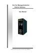
Introduction The Elinx EIR505 series of Industrial Managed Ethernet Switches provide powerful functionality in a small package. Designed for industrial applications, these switches are highly reliable. Features Conforms to IEEE 802.3 10Base-T, 802.
Package Contents 5 Port Managed Industrial Switch One DIN-Rail (attached to the switch) One Panel mount plate and six screws User manual 5 10/100TX with X-Ring Web Management Industrial switch Wall Mount Plate User Manual Screws DIN-Rail If any item is missing or damaged, contact B&B Electronics for a replacement. 2 Manual Documentation Number: EIR505-xx_5107m B&B Electronics Mfg Co Inc – 707 Dayton Rd - PO Box 1040 - Ottawa IL 61350 - Ph 815-433-5100 - Fax 815-433-5104 – www.bb-elec.
Hardware Description Physical Dimension (W x H x D) 2.13in x 5.31in x 4.13 in (54mm x 135mm x 105mm) Front Panel EIR505 Front Panel Reset Button The reset button is used to restart the reboot the switch or restore it to the factory default configuration. Restart: Press the button for 2 seconds and release. Set to factory default value: Press the button for 5 seconds and release.
Bottom View The bottom panel of the EIR-505-xx industrial switch consists of one terminal block connector with two DC power inputs and one DC IN power jack. Bottom Panel of the industrial switch DIP-switch The six position DIP-switch is used to configure the relay alarm operation mode and the master ring operation mode. The default value for each position is OFF. DIP Switch No Status Description OFF Disable port 1 Alarm ON Enable port Alarm.
ON Enable port Alarm. OFF Disable port Alarm ON Enable port Alarm. OFF Disable port Alarm ON Enable port Alarm. OFF Disable port Alarm ON Enable port Alarm. OFF Disable the master ring function. 3 4 5 6 Enable the switch as the ring master ON in the X-Ring group. LED Indicators There are 7 diagnostic LEDs located on the front panel. They provide real-time status information.
Off Green The switch is off or no power input is available The switch is the master of X-Ring group R.M.
RJ-45 Pin Assignments Pin Number Assignment 1 Tx+ 2 Tx- 3 Rx+ 6 Rx- All ports on this switch support automatic MDI/MDI-X operation. Straight-through cables can be used for all network connections. In straight-through cable, pins 1, 2, 3, and 6, at one end of the cable, are connected straight through to pins 1, 2, 3 and 6 at the other end of the cable. The table below shows the 10BASE-T/100BASE-TX MDI and MDI-X port pin outs.
Cross Over Cable Schematic Fiber Port There is one 100Base-FX port. The fiber port is SC type connector in multi mode (2Km) or single mode (30Km). Connect the fiber port as described below. ATTENTION This is a Class 1 Laser/LED product. Do not stare into the Laser/LED Beam. Cabling Use Category 5 cabling for RJ-45 port connections. The cable must be less than 328 ft (100 meters) long. 8 Use 8/125 or 9/125 um for single-mode fiber.
Kilometers are supported. Fuse 50 or 62.5/125 um for multi-mode fiber cable. Distances up to 2Kmare supported. Wiring the Power Inputs V- V+ V- V+ 1. Insert the positive and negative wires into the V+ and Vconnector on the terminal block connector 2. Tighten the wire-clamp screws [NOTE] Use 12~ 24 AWG wire. Manual Documentation Number: EIR505-xx_5107m B&B Electronics Mfg Co Inc – 707 Dayton Rd - PO Box 1040 - Ottawa IL 61350 - Ph 815-433-5100 - Fax 815-433-5104 – www.bb-elec.
Wiring the Fault Alarm Contact The fault alarm contact are located in the middle of terminal block connector as shown below. Insert the wires and set the Dipswitch to “ON”. When a power source fails or a link fault occurs, it will be detected and cause an open circuit. The following figure shows an application example for the fault alarm contact. 1A@24V Insert the wires into the fault alarm contact [NOTE] The wire range of terminal block is from 12~ +24 AWG.
Mounting Installation DIN-Rail Mounting Rear Panel of the switch DIN-Rail Use the screws to attach the DIN-Rail to the industrial switch To remove the DIN-Rail, reverse the step 1. Manual Documentation Number: EIR505-xx_5107m B&B Electronics Mfg Co Inc – 707 Dayton Rd - PO Box 1040 - Ottawa IL 61350 - Ph 815-433-5100 - Fax 815-433-5104 – www.bb-elec.com B&B Electronics – Westlink Commercial Park – Oranmore, Galway, Ireland – Ph +353 91-792444 – Fax +353 91-792445 – www.bb-europe.
12 1. First, insert the top of DIN-Rail into the track. 2. Then, lightly push the DIN-Rail into the track. 3. Ensure the DIN-Rail is tightly secured to the track. 4. To remove the industrial switch from the track, reverse steps above. Manual Documentation Number: EIR505-xx_5107m B&B Electronics Mfg Co Inc – 707 Dayton Rd - PO Box 1040 - Ottawa IL 61350 - Ph 815-433-5100 - Fax 815-433-5104 – www.bb-elec.
Panel Mounting Follow the steps below to mount the industrial switch with the Panel mount plate. 1. Remove the DIN-Rail from the industrial switch. 2. Place the wall Panel plate on the rear of the industrial switch. 3. Use the screws to attach the Panel plate to the industrial switch 4. Use the hook holes at the corners of the panel mount plate to attach the industrial switch to the panel. 5.
Hardware Installation . 1. Unpack the Industrial switch. 2. Ensure the DIN-Rail is tightly screwed to the Industrial switch. If not, refer to DIN-Rail Mounting section for DIN-Rail installation. To panel mount the Industrial switch, refer to Panel Mounting section. 3. Apply power to the switch (refer to the Wiring the Power Inputs section). The power LED will light. 4. Connect CAT 5 cables to the Industrial switch’s RJ-45 ports and to the network devices.
Network Application X-Ring Application The EIR505 series of Industrial Switches incorporate the X-Ring Protocol to ensure network reliability and system restoration within 300 ms in the event of a connection failure. The X-Ring algorithm is similar to the spanning tree protocol (STP) algorithm but it has faster recovery time. The following figure below is an example of an X-Ring application.
Coupling Ring Application If the network has more than one X-Ring group, the coupling ring function is used to connect them and add redundancy. This ensures that transmissions between the two ring groups will not fail. The figure below is an example of the coupling ring application. 16 Manual Documentation Number: EIR505-xx_5107m B&B Electronics Mfg Co Inc – 707 Dayton Rd - PO Box 1040 - Ottawa IL 61350 - Ph 815-433-5100 - Fax 815-433-5104 – www.bb-elec.
Dual Homing Application The Dual Homing function is used to prevent a connection loss between the X-Ring group and the upper level/core switch. Assign a port in each X-ring group to be the Dual Homing ports The Dual Homing function can only be used when the X-Ring function is active. Each X-Ring group can have one Dual Homing port. [NOTE] In the Dual Homing architecture, the upper level switches must have Rapid Spanning Tree protocol enabled.
Web-Based Management About Web-based Management The switch has an embedded HTML web site residing in flash memory. This site offers advanced management features and allows the switch to be configured from anywhere on the network. The web site is designed for Internet Explorer 5.0 and uses Java Applets to reduce bandwidth consumption, enhance access speed, and present an intuitive user interface. [NOTE] By default, IE5.0 and later versions do not allow Java Applets to activate sockets.
System Login 1. Launch Internet Explorer on the PC. 2. Enter “http:// “+” the IP address of the switch”, in the address window and then Press “Enter”. 3. The login screen will appear. 4. Enter the user name and password. 5. Press “Enter” or “OK”, the home screen will appear.
Port status Shows the status of each port Port: Displays the port number Type: Displays the speed and mode, ex: 100TX = 100Mbps Link: Displays the ports status (up or down) State: Displays the ports status (disabled or enabled). Unlinked is displayed as “off ” Negotiation: Displays the auto negotiation mode (auto or forced). Speed Duplex: Displays the port connection speed. “Config” is the configured value. “Actual” is the current value.
Port information interface Port Statistics Displays port statistics. Click Clear button to reset. Port Statistics Interface Manual Documentation Number: EIR505-xx_5107m B&B Electronics Mfg Co Inc – 707 Dayton Rd - PO Box 1040 - Ottawa IL 61350 - Ph 815-433-5100 - Fax 815-433-5104 – www.bb-elec.com B&B Electronics – Westlink Commercial Park – Oranmore, Galway, Ireland – Ph +353 91-792444 – Fax +353 91-792445 – www.bb-europe.
Port Control Used to set up the port. 1. Select the port by scrolling down the Port column. The current port information will be displayed in the table below. 2. State: Enables or disables the port. 3. Negotiation: Sets the negotiation mode to Auto, Nway (specify the speed/duplex of the port and enable auto-negotiation), or Forced. 4. Speed: Sets the transmit speed of the port 5. Duplex: Sets the port to full-duplex or half-duplex 6.
Switch Settings Used to assign the system name, location and to view system information System Name: Assigns a name to the switch. The maximum length is 64 bytes System Location: Assigns a physical location for the switch. The maximum length is 64 bytes System Description: Displays the description of switch.
Port Mirroring Port mirroring is a method to monitor traffic in switched networks. This is accomplished by mirroring the traffic going in and out of the monitored ports to a specifically designated port (the mirror port). 1. Port Mirroring Mode: Sets the mirror mode. Select disable to disable port mirroring. Select TX to monitor data being transmitted by a port. Select both to monitor port data being transmitted and received by a port. The default value is “Disable”. 2.
VLAN configuration A Virtual LAN (VLAN) can be thought of as a broadcast domain that exists within a switch or a defined set of switches. By grouping switch ports into VLANs, traffic flooding is limited since devices can only communicate directly with devices belonging to the VLAN. Creating a VLAN from a switch is the logical equivalent of reconnecting a group of devices to another Layer 2 switch. However, the network devices retain their same physical connection.
VLAN – Port Base interface 1. Click Add to add a new VLAN group. The EIR505 series supports up to 64 VLAN groups 26 2. Enter Group name, VLAN ID and select the members of VLAN group 3. Click Apply Manual Documentation Number: EIR505-xx_5107m B&B Electronics Mfg Co Inc – 707 Dayton Rd - PO Box 1040 - Ottawa IL 61350 - Ph 815-433-5100 - Fax 815-433-5104 – www.bb-elec.com B&B Electronics – Westlink Commercial Park – Oranmore, Galway, Ireland – Ph +353 91-792444 – Fax +353 91-792445 – www.bb-europe.
VLAN—Port Base Add interface 4. The VLAN group will be displayed after apply is clicked 5. Click 6. Use 7. Use Edit Next Page Delete to view the next VLAN group button to delete unwanted VLANs button to modify existing VLANs [NOTE] If the configuration is not saved, it will be lost when the switch is powered off 802.1Q VLAN Tagged-based VLAN is an IEEE 802.1Q specification which allows VLANs to be created across devices from different venders. IEEE 802.
uses a technique to insert a “tag” into the Ethernet frame. The tag contains a VLAN Identifier (VID). When the 802.1Q VLAN is enabled, all ports on the switch belong to a default VLAN (VID 1). The default VLAN can’t be deled. The EIR505 series will support up to 64 VLAN groups. 802.1q VLAN interface Basic 1. Click Add 2. Management VLAN ID: Used for Remote Management Security. When this option is selected, remote management is only available to the members of the indicated VLAN Group.
3. Group Name: assign a name for the new VLAN 4. VLAN ID: fill in a VLAN ID. The default is 1 5. From the Available ports box, select ports to add to the VLAN group and click Add button 802.1q VLAN –Add interface 6. Click Next to bring up the configuration interface: Manual Documentation Number: EIR505-xx_5107m B&B Electronics Mfg Co Inc – 707 Dayton Rd - PO Box 1040 - Ottawa IL 61350 - Ph 815-433-5100 - Fax 815-433-5104 – www.bb-elec.
7. Select outgoing frames as VLAN-Tagged frames or untagged and then click 30 Apply Port VID: Configure port VID settings 1. Port VLAN ID: enter the port VLAN ID 2. And then, click Apply 3. To reset to the default values, click Default button Manual Documentation Number: EIR505-xx_5107m B&B Electronics Mfg Co Inc – 707 Dayton Rd - PO Box 1040 - Ottawa IL 61350 - Ph 815-433-5100 - Fax 815-433-5104 – www.bb-elec.
802.1q VLAN – Port VLAN ID interface [NOTE] If the configuration is not saved, it will be lost if the switch is powered off. IP Address Configure the IP Settings and DHCP client function DHCP Client: Use to enable or disable the DHCP client function. When the DHCP client function is enabled, the industrial switch will be assigned an IP address from the network DHCP server.
Client is enabled. The default IP is 192.168.10.1. Subnet Mask: Assign the subnet mask of the IP address. This is not required if the DHCP Client is enabled. Gateway: Assign the network gateway. The default gateway is 192.168.10.254. Click Apply IP configuration interface SNTP Configuration SNTP (Simple Network Time Protocol) allows the switch to synchronize its time with an SNTP Server. 1. SNTP Client: Enable or Disable SNTP 2.
ADT - Atlantic Daylight -3 hours 9 am -4 hours 8 am -5 hours 7 am -6 hours 6 am -7 hours 5 am -8 hours 4 am -9 hours 3 am -10 hours 2 am -11 hours 1 am +1 hour 1 pm AST - Atlantic Standard EDT - Eastern Daylight EST - Eastern Standard CDT - Central Daylight CST - Central Standard MDT - Mountain Daylight MST - Mountain Standard PDT - Pacific Daylight PST - Pacific Standard ADT - Alaskan Daylight ALA - Alaskan Standard HAW - Hawaiian Standard Nome, Alaska CET - Central European FWT - Fren
European Winter SWT - Swedish Winter EET - Eastern European, Russia +2 hours 2 pm +3 hours 3 pm ZP4 - Russia Zone 3 +4 hours 4 pm ZP5 - Russia Zone 4 +5 hours 5 pm ZP6 - Russia Zone 5 +6 hours 6 pm +7 hours 7 pm +8 hours 8 pm +9 hours 9 pm +10 hours 10 pm +12 hours Midnight Zone 1 BT - Baghdad, USSR Zone 2 WAST - West Australian Standard CCT - China Coast, USSR Zone 7 JST - Japan Standard, Russia Zone 8 EAST - East Australian Standard GST Guam Standard, Russia Zone 9 IDLE - Internat
[NOTE] If the configuration is not saved, it will be lost when the switch is powered off. SNTP Configuration IP Security IP security function grants 10 specific IP addresses permission to access the switch through a web browser for the switch management. 1. Enable the IP Security: Mark the check box to enable 2. Security IP 1 ~ 10: Enter up to 10 specific IP address. 3. Click Apply [NOTE] If the configuration is not saved, it will be lost when the switch is powered off.
IP Security Interface RSTP Configuration The Rapid Spanning Tree Protocol (RSTP) is an evolution of Spanning Tree Protocol (STP). It provides a faster spanning tree convergence after a topology change. The switch will auto detect a device that is running STP or RSTP protocol. System Configuration Modify RSTP state parameters RSTP mode: Enable or disable RSTP function. Priority (0-61440): a value used to identify the root bridge.
Hello Time (1-10): The time that the control switch sends out a BPDU packet to check RSTP status. Enter a value between 1 and 10. Forward Delay Time (4-30): The number of seconds a port waits before changing from its Rapid Spanning-Tree Protocol learning and listening states to the forwarding state. Enter a value between 4 through 30. Click Apply [NOTE] 1. Use the following rule to configure the MAX Age, Hello Time, and Forward Delay Time.
Per Port Configuration Configure path cost and priority of every port 1. Select the port in Port column 2. Path Cost: The cost of the path to the other bridge from this transmitting bridge at the specified port. Enter a number 1 through 200000000 3. Priority: Network Priority. Enter a number from 0 to 240. The value must be a multiple of 16 4.
RSTP – Per Port Configuration interface X-Ring X-Ring provides network redundancy similar to the Spanning Tree and Rapid Spanning Tree Protocols. However, recovery time is greatly reduced when the X-Ring protocol is used. The protocol identifies one switch as the Ring Master. Packets are blocked from the redundant path unless a ring member becomes disconnected from the rest of the network. When this happens, the protocol automatically restores connectivity using the redundant path.
ring master has the rights to negotiate and place a command to other switches in the X-Ring group. If more than one switch is in master mode, the software will select the switch with lowest MAC address number as the ring master. An LED on the front panel indicates that the switch is the ring master. Coupling ring is used to connect 2 or more X-Ring groups providing a redundant back-up Dual homing is used to recover from a connection loss between an X-Ring group and the upper level/core switch.
X-Ring Interface [NOTE] 1. When the X-Ring function is enabled, the RSTP function must be disabled. 2. If the configuration is not saved, it will be lost when the switch is powered off. QoS Configuration Qos Policy: select the Qos policy rule ¾ Using the 8,4,2,1 weight fair queue scheme: The switch will follow 8:4:2:1 rate to process priority queue from Highest to lowest.
¾ COS only: The port will follow the COS priority assigned ¾ TOS only: The port will follow the TOS priority assigned ¾ COS first: The port will follow COS priority first, and then another priority rule ¾ TOS first: The port will follow TOS priority first, and then another priority rule COS priority: Set the COS priority level 0~7 TOS priority: The system provides 0 to 63 TOS priority levels. Each level has 4 types of priority – high, mid, low, and lowest. The default value is “Lowest”.
QoS configuration Interface IGMP The Internet Group Management Protocol (IGMP) is an internal protocol of the Internet Protocol (IP) suite. IP manages multicast traffic by using switches, routers, and hosts that support IGMP. Enabling IGMP allows the ports to detect IGMP queries and report packets and manage IP multicast traffic through the switch.
Message Description A message sent from an IGMP router or switch Query requesting a response from each host belonging to the multicast group. A message sent by a host indicating that the host Report wants to be or is a member of a given group. A message sent by a host indicating that the host Leave Group has is no longer a member of a specific multicast group. [NOTE] If the configuration is not saved, it will be lost when the switch is powered off.
Security Manager Use to change the web management login user name and password. 1. User name: enter the new user name(The default is “root”) 2. Password: enter the new password(The default is “root”) 3. Confirm password: reenter the new password 4. Click Apply [NOTE] If the configuration is not saved, it will be lost when the switch is powered off.
TFTP Restore Configuration interface TFTP Backup Configuration Save current flash ROM value to the TFTP server 1. TFTP Server IP Address: Enter the TFTP server IP 2. Backup File Name: Enter the file name 3. Click Apply TFTP Backup Configuration interface TFTP Update Firmware Use to update firmware. Ensure the TFTP server is ready and the firmware image is stored on the TFTP server, 46 1. TFTP Server IP Address: Enter the TFTP server IP Address 2.
TFTP Update Firmware interface Factory Default Reset the Switch to the default configuration. NOTE: The IP Address, subnet mask, default gateway, username, and password will remain as configured by the user. Click Default Factory Default interface System Reboot Reboot the switch in software reset Click Reboot System Reboot interface Manual Documentation Number: EIR505-xx_5107m B&B Electronics Mfg Co Inc – 707 Dayton Rd - PO Box 1040 - Ottawa IL 61350 - Ph 815-433-5100 - Fax 815-433-5104 – www.
Save Configuration Save the configuration to flash memory. If the switch is powered off without saving the configuration, all changed configuration will lost Click Save Flash Save Configuration Interface Rate Control Set up each port’s bandwidth rate and packet limitation type Limit Packet type: Select the packet type to filter. The packet filter types are all packet types, broadcast/multicast/unknown, unicast packets, broadcast/multicast packets, and broadcast packet only.
[NOTE] 1. If the configuration is not saved, it will be lost when the switch is powered off. 2. Qos and Rate control cannot exist at the same. Rate Control Interface Manual Documentation Number: EIR505-xx_5107m B&B Electronics Mfg Co Inc – 707 Dayton Rd - PO Box 1040 - Ottawa IL 61350 - Ph 815-433-5100 - Fax 815-433-5104 – www.bb-elec.com B&B Electronics – Westlink Commercial Park – Oranmore, Galway, Ireland – Ph +353 91-792444 – Fax +353 91-792445 – www.bb-europe.
Trouble shooting Verify the power supply is correct (12-48V DC) Do not exceed 48V DC. Ensure the proper UTP cable is used for RJ-45 connections: 100Ω Category 3, 4 or 5 cable for 10Mbps connections or 100Ω Category 5 cable for 100Mbps connections. Ensure that the length of any twisted-pair connection does not exceed 328 feet (100 meters). 50 LED Indicators: Assist in identifying problems.
Technical Specification IEEE 802.3 10Base-T Ethernet IEEE 802.3u 100Base-TX Fast Ethernet IEEE802.3x Flow Control and Back-pressure IEEE802.1d spanning tree / IEEE802.1w rapid Standards spanning tree IEEE802.1p class of service IEEE802.
LED Per port: Link/Activity (Green), Full duplex/Collision (Yellow) Per unit: Power (Green), Power 1 (Green), Power 2 (Green), Fault (Yellow), Master (Green) 10Base-T: 2-pair UTP/STP Cat. 3, 4, 5 cable Network Cable EIA/TIA-568 100-ohm (100m) 100Base-TX: 2-pair UTP/STP Cat. 5 cable EIA/TIA-568 100-ohm (100m) SC (Multi-mode): 50/125um~62.
port based Quality of service Tag based IPv4 Type of service 300 ms Recovery Time X-Ring Port based VLAN and IEEE802.1Q Tag VLAN. VLAN Both port based and Tag based VLAN groups (up to 64). Spanning tree IEEE802.1d spanning tree and IEEE802.1w rapid spanning tree. IGMP IGMP v1 and Query mode. Up to 256 groups. SNTP Simple Network time protocol Management IP security Port mirror IP address security to prevent intrusion TX packet only or both TX and RX packet.
Install DIN rail and panel mount Alarm One 24VDC, 1A relay output. TFTP firmware update Firmware update TFTP configuration backup and restore. DHCP client function to obtain the IP address DHCP client from a DHCP server.
FCC Class A, CE EN6100-4-2, CE EN6100-4-3, CE EN-6100-4-4, EMI CE EN6100-4-5, CE EN6100-4-6 EN60950 Safety Stability testing IEC60068-2-32 (Free fall), IEC60068-2-27 (Shock), IEC60068-2-6 (Vibration) Manual Documentation Number: EIR505-xx_5107m B&B Electronics Mfg Co Inc – 707 Dayton Rd - PO Box 1040 - Ottawa IL 61350 - Ph 815-433-5100 - Fax 815-433-5104 – www.bb-elec.com B&B Electronics – Westlink Commercial Park – Oranmore, Galway, Ireland – Ph +353 91-792444 – Fax +353 91-792445 – www.bb-europe.