
Switch User Manual


10
Manual Documentation Number: EIR505-xx_5107m
B&B Electronics Mfg Co Inc – 707 Dayton Rd - PO Box 1040 - Ottawa IL 61350 - Ph 815-433-5100 - Fax 815-433-5104 – www.bb-elec.com
B&B Electronics – Westlink Commercial Park – Oranmore, Galway, Ireland – Ph +353 91-792444 – Fax +353 91-792445 – www.bb-europe.com
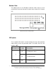
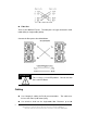
Wiring the Fault Alarm Contact
The fault alarm contact are located in the middle of terminal block connector
as shown below. Insert the wires and set the Dipswitch to “ON”. When a
power source fails or a link fault occurs, it will be detected and cause an
open circuit. The following figure shows an application example for the fault
alarm contact.
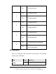
[NOTE] The wire range of terminal block is from 12~ +24 AWG.
Fault Alarm Contact
24V DC Buzzer 24V Battery
The open circuit will form when the
power failure or port link failure.
The fault alarm device will send a
warning signal to warn the user, ex:
alarm sound or flash light.
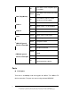
Insert the wires into the fault alarm contact
1A@24V