Models ESP904, ESP904E Quad-Port Multi-Interface Ethernet Serial Server (RS-232/422/485) Manual Documentation Number: ESP904-0504 B&B Electronics Mfg Co Inc – 707 Dayton Rd - PO Box 1040 - Ottawa IL 61350 - Ph 815-433-5100 - Fax 815-433-5104 – www.bb-elec.com B&B Electronics Ltd – Westlink Commercial Park – Oranmore, Galway, Ireland – Ph +353 91-792444 – Fax +353 91-792445 – www.bb-europe.
International Headquarters B&B Electronics Mfg. Co. Inc. 707 Dayton Road P.O. Box 1040 Ottawa, IL 61350 USA Phone (815) 433-5100 -- General Fax (815) 433-5105 Website: www.bb-elec.com Sales e-mail: orders@bb-elec.com -- Fax (815) 433-5109 Technical Support e-mail: support@bb.elec.com -- Fax (815) 433-5104 European Headquarters B&B Electronics Ltd. Westlink Commercial Park Oranmore, Co. Galway, Ireland Phone +353 91-792444 -- Fax +353 91-792445 Website: www.bb-europe.com Sales e-mail: sales@bb-europe.
Automatic Installation......................................................................................... 19 Manual Installation............................................................................................. 19 CHAPTER 4: USING ESP MANAGER................................................................. 23 Table of Contents HARDWARE SETUP: ................................................................................................. 23 SOFTWARE SETUP:................................
UPGRADING VIA ESP904 MANAGER ....................................................................... 47 Preparing the Software ....................................................................................... 47 Upgrading the Firmware .................................................................................... 48 CHAPTER 9: USING CONSOLE MODE ............................................................. 51 CONSOLE MODE SETUP .....................................................................
Table of Figures Figure 1. The VLINX ESP904 Quad-Port Ethernet Serial Server ................................ 1 Figure 2. Quick Start Hardware Setup ......................................................................... 4 Figure 3. The ESP Manager Window ........................................................................... 5 Figure 4. The Server Properties Window ..................................................................... 6 Figure 5. Configuring the Virtual COM Port ......................
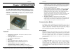
Introduction Introduction ESP904 can be attached to a network or to the Ethernet port of a computer (using a crossover cable). Non-Windows users can configure it in the Console Mode using an RS-232 port, VT100 Terminal Emulation program and an RS-232 crossover cable. Telnet also can be used to access the setup configuration menu. Chapter 1: INTRODUCTION The VLINX Model ESP904 Quad-Port Ethernet Serial Server provides Ethernet to Serial connections for RS-232, RS-422 or RS-485 devices.
Introduction Introduction After connection, the LAN is transparent to the program and serial device. Applications are able to work just as if the serial device is connected directly to a physical COM port on the computer. The virtual COM port software converts the application’s data into IP packets, sends it across the network to the ESP904, which converts the IP packet back to serial data and sends the data out a serial port located on the ESP904.
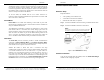
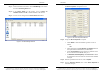
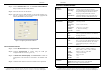
Introduction Introduction Step 4: Double click on the first ESP904 port on the list (4000) to bring up the Server Properties configuration screen. ESP904 Configuration Step 1: From the Windows Start menu, run the ESP Manager, then double click on the Searching Server icon. Step 2: In the Search Setup box that appears, click on Search all reachable servers, and OK, to find the ESP904 on the network. Step 3: A list of servers will appear in the Serial Server List window. Figure 4.
Introduction Introduction Install Virtual COM Ports on PC ESP904 Technical Data Step 1: From the Windows Start menu, run the Install Virtual COM Ports utility included with the VLINX software, Step 2: Search for all servers on the network Hardware and Included Accessories ESP904 Serial Server module Power Supply: 12 VDC/1A (tip positive/sleeve negative) Power Plug: (Area Dependent: North America 120VAC/60Hz, Europe/United Kingdom 220/240VAC/50Hz) Manual: Paper copy of this manual, PDF available CD-ROM
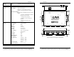
Introduction LAN: RJ-45 female 33.0 mm 5.73 mm countersink 43.0 mm 12.7 mm 3.7 mm hole 10 mm ESP904 4-Port Serial Server Port 4 Port 3 Port 2 DB-9M male DB-9M male DB-9M male Port 1 113.7 mm www.bb-elec.com 33.0 mm 6.3 mm 6.9 mm center hole 11.3 mm Software Selectable RS-232/422/485 4.7 mm 25.4 mm = 1 inch DB-9M male 161.5 mm 11 mm 29.0 mm Chapter 1 B&B Electronics Mfg Co Inc – 707 Dayton Rd - PO Box 1040 - Ottawa IL 61350 - Ph 815-433-5100 - Fax 815-433-5104 – www.bb-elec.
Installing the VLINX ESP Software Installing the VLINX ESP Software Chapter 2: MAKING THE HARDWARE CONNECTIONS ESP904 Connections, Indicators and Reset Switch The ESP904 has: Package Checklist The ESP904 4-port serial server is shipped with the following items included: 9 9 9 9 ESP904 Serial Server Module Power supply This manual CD-ROM disc with manual, VLINX ESP Manager and Virtual COM Driver software for Windows 98/ME/2000/XP/NT 4.
Installing the VLINX ESP Software Installing the VLINX ESP Software Serial Port Operational Modes Using the ESP Manager or the Console Mode Configuration Menu each serial port can independently be configured as RS-232 Mode, RS422 Mode or RS-485 Mode. Port 1 of the ESP904 also can be placed in Console Mode, Upgrade Mode or Default Mode. Port 1 default setting is Console Mode. Power Connector Plug the ultra-miniature phone plug from the included power supply into the power jack and then plug the supply in.
Installing the VLINX ESP Software Installing the VLINX ESP Software RS-232 Mode In RS-232 Mode the serial port is configured to support eight RS-232 signal lines plus Signal Ground and is configured as DTE like a computer. Signals are single ended and referenced to Ground. To use handshaking, Flow Control must be set to RTS/CTS during Configuration. Note: Refer to Appendix A for RS-232 connection pin-outs.
Installing the VLINX ESP Software Installing the VLINX ESP Software ESP904 Serial Port Connector Pin-outs Pin-outs for RS-232, RS-422 and RS-485 operation are shown below.
Installing the VLINX ESP Software Installing the VLINX ESP Software Chapter 3: INSTALLING THE VLINX ESP SOFTWARE Figure 13. The Install Shield Wizard Window The Windows-based ESP Manager and Virtual COM Port software makes configuration fast and easy. If using Windows, installing the ESP Manager software and setting up virtual COM ports to configure the ESP904 is recommended. Step 2: When the VLINX ESP Setup window appears, click Next.
Installing the VLINX ESP Software Installing the VLINX ESP Software Figure 16. The Install Shield Wizard Complete Window Step 4: Select Finish when the Install Shield Wizard Complete window appears. After Finish, the Install window closes. Step 5: Start the ESP Manager software: Start → Programs → B&B Electronics → VLINX → ESP Servers → VLINX ESP Manager. Step 6: If the ESP904 is not already connected to the network or to the Ethernet port on the computer, connect it, and then apply power.
Using ESP Manager Using ESP Manager Chapter 4: USING ESP MANAGER The ESP Manager software allows: • Searching for servers connected to the network • Displaying and changing the configuration of those servers • Installing virtual COM ports on a computer • Displaying and configuring virtual COM ports • Uninstalling virtual COM ports on a computer • Upgrading the ESP904 firmware Figure 18.
Using ESP Manager Using ESP Manager The following window should appear: The Virtual COM List contains the following information: • COM Name • IP Address • Protocol • Port • Flow Control • Status Server Icons Section Firmware Upgrade Used when downloading new firmware to the ESP Server. Figure 19. The VLINX ESP Manager Window Note: See Chapter 8 for more information on upgrading firmware.
Using ESP Manager Using ESP Manager Protocol Searching Server Displays the currently selected TCP or UDP mode for the ESP904 server. Step 4: To find the ESP904 on the network, click on Searching Servers (under the Servers menu or the icon on the left side of the screen). The Search Setup box will appear. COM Name Displays the number of the COM port mapped to each ESP904 port.
Using ESP Manager Using ESP Manager The Server Properties window is used to configure and store the Server configuration settings. Details for setting Properties are shown in the next chapter. Step 7: After configuring as needed, click Update to store the configuration in the server. The following window will appear: Figure 22. The vcomui Window Step 8: Click Yes to restart. The server is automatically reset.
Server Properties Configuration Server Properties Configuration Chapter 5: CONFIGURING THE ESP904 SERVER PROPERTIES IP Address Software or hardware attempting to access the ESP904 server via the network must know the IP Address of the server. A static IP address is retained and remains the same each time the server is powered up or starts/restarts. The default IP address of the ESP904 server is printed on a label on the bottom cover of the ESP904.
Server Properties Configuration Server Properties Configuration Server Serial Port (Select 1 to 4) TCP/UDP Protocol The configuration for each port is displayed one at a time. In the ESP Manager, double-click on the port in the Serial Server List. This brings up the Server Properties window for that port. Make any desired changes to the configuration and then click on Update. Only the settings for the port shown are stored.
Server Properties Configuration Server Properties Configuration Update/Save Updating using ESP Manager If using the Server Properties screen for configuration, click the Update button to store the configuration settings for each serial port separately. This also resets the ESP904 Server. Click on Searching Server to download and confirm the new settings. Saving using the Configuration Menu If using the Configuration Menu in Telnet or Console Mode, Tab to Save, then press Enter.
Installing Virtual COM Port Installing Virtual COM Port The program searches the LAN for all available ESP901/ESP902/ESP904 Serial Servers. When complete, the Found Server window appears and displays a list of the servers that were found. Chapter 6: INSTALLING VIRTUAL COM PORTS The Virtual COM Port feature allows Windows platform software, using standard API calls, to be used in an Ethernet application. The Install Virtual COM port software adds an ESP904 (COM#) port to the computer.
Installing Virtual COM Port Installing Virtual COM Port Matching the ESP904 and Virtual COM Port Settings The settings of the virtual COM ports in the Device Manager and the ESP904 Configuration menu must match. If the settings do not match, the virtual COM ports will not work. If these settings are changed in the Device Manager, it will only affect the operation of the virtual COM port. It will not change the settings stored in the ESP904. Use the ESP Manager to change the ESP904 Server settings.
Installing Virtual COM Port Installing Virtual COM Port . Figure 28. The VLINX ESP (COM3) Properties Window Step 4: Select the Configuration or Port Settings tab. This screen allows the settings to be changed if necessary. Click on Cancel to keep the existing settings. Step 5: Click on OK to change the settings. Use Refresh in the Device Manager if Windows does not auto refresh.
Removing a Virtual COM Port Removing a Virtual COM Port Chapter 7: REMOVING VIRTUAL COM PORTS Step 3: Select Uninstall Virtual COM button. The Manager will ask for conformation. Select OK to complete the uninstall procedure. The ESP904 Management software Uninstall Virtual COM Port feature will remove a mapped COM port in the Device Manager of Windows 2000 and XP operating systems. It may also be removed in the Device Manager of Windows 98, ME, NT, 2000, and XP.
Removing a Virtual COM Port Removing a Virtual COM Port Step 4: Highlight ESP904 (COM #) to be removed, go the Action tab at the top of window and select Uninstall. A confirm Device Removal window will appear. Figure 31. The Control Panel Window Step 3: Select Device Manager in the Systems Properties window. In the Device Manager window select the + next to Ports (COM LPT) to expand. Figure 33. Confirm Device Removal Step 5: Select OK to proceed.
Upgrade Mode Upgrade Mode Chapter 8: UPGRADING THE ESP904 FIRMWARE Upgrading the Firmware Step 5: Double-click on the Firmware Upgrade icon (or click on the Server menu and Firmware Upgrade) Step 6: In the Upgrade window, select Browse. The Open dialogue box will appear. Locate the folder that contains the firmware .hex file. Select the file and click Open. The Open dialogue box will disappear.
Upgrade Mode Upgrade Mode Step 10: Upgrade progress will be shown until the Upgrade finished! message is shown. Select OK. Figure 35. Upgrading in Progress Manual Documentation Number: ESP904-0504 Chapter 8 B&B Electronics Mfg Co Inc – 707 Dayton Rd - PO Box 1040 - Ottawa IL 61350 - Ph 815-433-5100 - Fax 815-433-5104 – www.bb-elec.com B&B Electronics Ltd – Westlink Commercial Park – Oranmore, Galway, Ireland – Ph +353 91-792444 – Fax +353 91-792445 – www.bb-europe.
Using Console Mode Using Console Mode Chapter 9: USING CONSOLE MODE Before the ESP904 is installed on a LAN the Console Mode can be used to change the settings from the defaults. The ESP904 is shipped with Port 1 set in the Console Mode. Connect a crossover (null modem) cable between the ESP904 Port1 and the COM port on the Computer. Note: See Chapter 5 for details of each Server Property Settings. Console Mode Setup Step 1: Apply power to the ESP904. The power and ready LED will light.
Using Console Mode Using Console Mode Using a Password If a password is used it must be entered before the Configuration screen can be seen. If the server is accessed with a password but no changes are made, Reset to end before disconnecting. Figure 37. Saving and Restarting the Configuration Figure 38. Assigning a Password The restart message will appear. Step 6: Select Yes to save changes. This is necessary to write the settings to the server. Step 7: To view the changes press the space bar.
Using the Web Server Using the Web Server Navigate and change properties as required using the mouse and keyboard. Chapter 10: USING THE WEB SERVER To change serial port properties, click on Uart Port on the left side of the browser window. The following page will appear: The Web Server can be used to configure the ESP904 from any web browser software (such as Internet Explorer). Server properties can be set up using two browser pages. Note: See Chapter 5 for details on Server Properties.
RS-232 Connections RS-232 Connections RS-232 Straight-through Cable Connections APPENDIX A: RS-232 CONNECTIONS In the RS-232 mode, the ESP904’s ports are configured as DTEs like a computer.
RS-232 Connections RS-232 Connections RS-232 Straight-through DB-9 to DB-25 Conversion Connections RS-232 DTE Loopback Connections Figure 46. Loopback Connections for RS-232 For Transmit and Receive loopback, connect only those lines. Figure 44. Connections for a DB-9 to DB-25 Straight-through Cable When Flow Control setting on the Serial Server is set for RTS/CTS, those lines must be looped. Usually DTR and DSR must also be looped.
RS-422 Connections RS-422 Connections ESP904 pin-out in RS-422 mode APPENDIX B: RS-422 CONNECTIONS RS-422 Signal Names ESP904 DB-9 Pin-outs in RS-422 Mode RS-422 Signal Name Direction RS-422 DB9M Pin Receive Data A (−) In RXDA (−) 1 Receive Data B (+) In RXDB (+) 2 Transmit Data B (+) Out TXDB (+) 3 Transmit Data A (−) Out TXDA (−) 4 Signal Ground --- GND 5 Clear to Send A (−) In CTSA (−) 6 Clear to Send B (+) In CTSB (+) 7 Request to Send B (+) Out RTSB (+) 8 Reque
RS-422 Connections RS-422 Connections Figure 49. Loopback Connections for RS-422 The RS-485 Connections are half duplex, either Receive or Transmit, so another half duplex device must be used to check operation. Figure 50. RS-422 Connection with No Flow Control Manual Documentation Number: ESP904-0504 Appendix B B&B Electronics Mfg Co Inc – 707 Dayton Rd - PO Box 1040 - Ottawa IL 61350 - Ph 815-433-5100 - Fax 815-433-5104 – www.bb-elec.
RS-485 Connections RS-485 Connections To connect 4-Wire RS-485 devices, the RS-422 Mode can be used provided the ESP904 will be connected as a master in a single master system. If using multiple masters, the ESP904 cannot be used, as it does not tri-state the transmitter in RS-422 mode.
Network Connections Network Connections APPENDIX D: NETWORK CONNECTIONS Crossover Ethernet Cable RJ-45 Pin-out Standard Ethernet Cable RJ-45 Pin-out RJ-45 Pin Signal Wire Color RJ-45 Pin 1 TX+ White-Green 1 2 TX+ Green 2 3 RX+ White-Orange 3 4 Not used Blue 4 5 Not used White-Blue 5 6 RX- Orange 6 7 Not used White-Brown 7 8 Not used Brown 8 RJ-45 Pin Signal Wire Color RJ-45 Pin 1 TX+ White-Green 3 2 TX+ Green 6 3 RX+ White-Orange 1 4 Not used Blue