(RS-232/422/485) Vlinx Wireless Serial Servers Models: ESR901W232, ESR901W485, ESR902W, ESR904W Documentation Number: ESR90xW-4905m pn#6876-rev001 B&B Electronics Mfg Co Inc – 707 Dayton Rd - PO Box 1040 - Ottawa IL 61350 - Ph 815-433-5100 - Fax 815-433-5104 – www.bb-elec.com B&B Electronics Ltd – Westlink Commercial Park – Oranmore, Galway, Ireland – Ph +353 91-792444 – Fax +353 91-792445 – www.bb-europe.
International Headquarters B&B Electronics Mfg. Co. Inc. 707 Dayton Road Ottawa, IL 61350 USA Phone (815) 433-5100 -- General Fax (815) 433-5105 Website: www.bb-elec.com Sales e-mail: orders@bb-elec.com -- Fax (815) 433-5109 Technical Support e-mail: support@bb.elec.com -- Fax (815) 433-5104 European Headquarters B&B Electronics Ltd. Westlink Commercial Park Oranmore, Co. Galway, Ireland Phone +353 91-792444 -- Fax +353 91-792445 Website: www.bb-europe.com Sales e-mail: sales@bb-europe.
© 2005 B&B Electronics. No part of this publication may be reproduced or transmitted in any form or by any means, electronic or mechanical, including photography, recording, or any information storage and retrieval system without written consent. Information in this manual is subject to change without notice, and does not represent a commitment on the part of B&B Electronics.
CHAPTER 5: ADJUSTING THE BEHAVIOR OF DEVICE COMMUNICATION PORTS ................................................................................. 21 Table of Contents CHAPTER 1: INTRODUCTION....................................................................... 1 ABOUT YOUR VLINX ESR90XW WIRELESS SERIAL SERVER ................................... 1 Features ................................................................................................................ 2 Communication Modes ...............
Introduction Chapter 1: Introduction Features Introduction • Backward compatibility with 802.
Introduction Introduction 802.11 Wireless Networking Virtual COM Mode IEEE 802.11 is a set of standards that defines how multiple devices can communicate on a wireless network. The standard has grown into a set of several standards that define various features and functions. The 802.11g standard defines the physical and data link layers for a wireless network using the 2.4 GHz frequency band, a band that does not require licensing. As a part of the IEEE family of standards, 802.
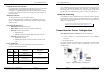
Introduction Introduction ESR90xW Startup Procedure IEEE 802.11g Setup and configuration of your Vlinx ESR90xW wireless serial server is fast, straightforward and simple. You have several options from which to choose. The following procedure outlines an easy way to get your server set up and operational. IEEE 802.11g standard specifies a WLAN that operates on the 2.4 GHz band at data rates up to 54 Mbps, but is backward compatible with the earlier 802.11b standard (which operates at up to 11 Mbps).
Introduction Introduction 4. Set Up PC 1. Configure the PC to work in the 192.168.0.x private address range 2. Open a web browser 3. Enter 192.168.0.200 into the address bar of the browser Figure 1. Direct Connection for Configuration 3. Power Up 1. Apply power to the ESR90xW 2. Front panel LED will illuminate with the following sequence: Figure 3. a. Power LED will always be lit while device is powered b. Signal Strength LED – White for 5 seconds, blink yellow/Red and go dark. c.
Vlinx ESR90xW Hardware Vlinx ESR90xW Hardware Hardware Features Chapter 2: Vlinx ESR90xW Hardware Indicators Power LED Package Checklist Red: Indicates the device is receiving power from an external source Vlinx ESR90xW Wireless Serial Servers are shipped with the following Signal Strength LED items included: Tri-color: Indicates the connection quality: 9 9 9 A Vlinx ESR901W232, ESR901W485, ESR902W or ESR904W Wireless Serial Server This Operation Manual CD-ROM disc with Device Detection Software
Vlinx ESR90xW Hardware Vlinx ESR90xW Hardware Connectors RS-485 Receiver Biasing Configuration Port Connector Vlinx ESR90xW wireless serial servers provide built-in receiver biasing on RS-485 ports (includes the 902W485 port, 902W Port 2 and 904W Ports 2 and 4). The Data(+) line is pulled up to 3.3V supply using a 4.7 kΩ resistor and the Data(-) line is pulled down to ground, also using a 4.7 kΩ resistor.
Vlinx ESR90xW Hardware Vlinx ESR90xW Hardware For wireless configuration, or for typical infrastructure mode operation, the Vlinx ESR90xW communicates with a wireless access point, which is connected to a PC via a wired network. Figure 7. Connection via the Wireless LAN Other Hardware Connections Serial tunneling can occur between two ESR90xW serial servers communicating with individual access points and across a wired network. Figure 8.
Web Console Chapter 4: Web Console You can change the Device Name of the serial server by typing in a different name Device Configuration via Web Console The Web Console can be used to configure your Vlinx ESR90xW Wireless Serial Server from any web browser software (such as Internet Explorer, Mozilla Firefox or Netscape). Server properties can be set up using six browser pages: Main, Serial, Network, Wireless, User and Status.
Web Console Web Console • Connection Protocol (RAW Client, RAW Server, Virtual COM Port Server, RFC2217 Client) • Server (Remote) IP Address • Server (Remote) Port • Local Port • Send Serial Data to Ethernet… conditions For explanations of these configuration parameters see Adjusting the behavior of device communication ports. Configuring Network Properties To view or change network properties, click Network on the Web Console banner. The Device Network Settings appears.
Web Console Web Console Figure 13. The Vlinx Web Console Users Page Using Device Status Information To view or change device status properties, click Status on the Web Console banner. The following page will appear: Figure 14. The Vlinx Web Console Status Page Documentation Number: ESR90xW-4905m Chapter 4 B&B Electronics Mfg Co Inc – 707 Dayton Rd - PO Box 1040 - Ottawa IL 61350 - Ph 815-433-5100 - Fax 815-433-5104 – www.bb-elec.
Device Communication Ports Device Communication Ports Polling Strings Chapter 5: Adjusting the Behavior of Device Communication Ports There is a significant difference between serial and Ethernet data communications. Data that comes in through the Ethernet is presented to the device in the form of very distinct packets.
Device Communication Ports Device Communication Ports VCOM Port Setup Chapter 6: Device Discovery and Virtual COM Ports To install and manage Virtual COM ports, Serial IP software will be provided. The software will be installed in the start menu at Serial-IP. To run the setup software, choose Control Panel and this screen will be displayed: Device Detection Utility To find devices on a wireless network, run the Device Detection Utility.
Vlinx ESR90xW Technical Data Vlinx ESR90xW Technical Data Parity: Appendix A: Vlinx ESR90xW Technical Data Data Bits: 5, 6, 7 or 8 Stop Bits: 1, 1.5 or 2 Set-up Options: Product Specifications Serial Server Model: Manual: Dimensions Power Supply Voltage Requirements: Configuration Modes: Vlinx ESR901W232, Vlinx ESR901W485, Vlinx ESR902W or Vlinx ESR904W Configuration Port: Paper copy of this manual, PDF available Wireless Network Interface: 6.85 x 5.72 x 2.27 in (17.4 x 14.5 x 5.
Vlinx ESR90xW Technical Data Default Server Properties Server Name Serial Number: Password: DHCP: Vlinx ESR90xW Dimensional Diagrams Vlinx ESR901W232 or Vlinx ESR901W485 or Vlinx ESR902W or Vlinx ESR904W (printed on bottom of unit) Blank Disable IP Address: 192.168.0.200 Net Mask: 255.255.255.0 Gateway: 192.168.0.
Vlinx ESR90xW Technical Data Vlinx ESR90xW Technical Data Figure 17. Dimensional Diagram of the Vlinx 902W Figure 18. Dimensional Diagram of the Vlinx 904W Documentation Number: ESR90xW-4905m Appendix A B&B Electronics Mfg Co Inc – 707 Dayton Rd - PO Box 1040 - Ottawa IL 61350 - Ph 815-433-5100 - Fax 815-433-5104 – www.bb-elec.com B&B Electronics Ltd – Westlink Commercial Park – Oranmore, Galway, Ireland – Ph +353 91-792444 – Fax +353 91-792445 – www.bb-europe.
RS-232/422/485 Connections RS-232/422/485 Connections Appendix B: RS-232/422/485 Connections Terminal Block Pin-out for RS-422 and RS-485 (Vlinx ESR901W485 only) DB-9 Pin-outs for RS-232 and RS-232/422/485 Connections TX DB (+ ) TX RX DA DB (-) (+ )/D ata RX (+ DA ) (-) /D ata (-) DB-9M RS-232 RS-232 DTE RS-422 Pin Signal Name 1 Carrier Detect DCD In TXDA(-) 2 Receive Data RXD In TXDB(+) GN D RS-485 3 Transmit Data TXD Out RXDB(+) DATA B(+) 4 Data Terminal Ready DTR Out R
RS-232/422/485 Connections RS-232/422/485 Connections 1 2 3 4 Signal Name Terminal AC Power Supply 1 (24 VAC) AC Power Supply 2 (24 VAC) DC Gnd 3 DC Power Supply 4 (+12 VDC to 30 VDC) Figure 21. Terminal Block Pin-out for Vlinx ESR90xW Power Supply Connection Documentation Number: ESR90xW-4905m Appendix B B&B Electronics Mfg Co Inc – 707 Dayton Rd - PO Box 1040 - Ottawa IL 61350 - Ph 815-433-5100 - Fax 815-433-5104 – www.bb-elec.
Configuration Port Connections Configuration Port Connections Appendix C: Configuration Port Connections RJ-45 Pin-out for Configuration Port Connection The Configuration Port on the Vlinx ESR90xW Wireless Serial Servers is wired as a standard Ethernet connector. However, this port is intended for direct connection to a PC for configuration purposes only and is not to be connected to a network. A standard Ethernet cable can be used to connect the PC to the Configuration Port.
Declaration of Conformity DECLARATION OF CONFORMITY Manufacturer’s Name: B&B Electronics Manufacturing Company International Headquarters Manufacturer’s Address: P.O. Box 1040 B&B Electronics Mfg. Co. Inc.