
Product data


26
MODBUSTM Networking
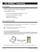
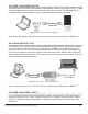
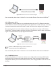
Figure 25. USB / RJ-11 Connection Diagram
Once connected, please refer to Section 5 on how to make Local Connections in MSView
TM
.
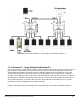
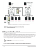
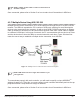
4.2.6 Multiple Device Using EIA-485
In an EIA-485 network, each device connects via a serial to EIA-485, 4 wire converter. Each con-
verter, such as Morningstar’s RSC-1 model, is powered by a DC power source. Refer to Section
2.1.2 for more information on the RSC-1 adapter. Power +/- is applied to the adapter as in Figure
26 below. The data connection A of all the adapters are wired together, as are all the B data con-
nections. Figure 26 illustrates how properly to connect equipment to the EIA-485 bus.
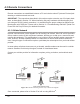
Figure 26. Multiple Device EIA-485 Bus Connection Diagram