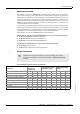
Title OPERATING INSTRUCTIONS FLOWSIC600 Ultrasonic Gas Flow Meter Ultrasonic Gas Flow Meter for Custody Transfer and Process Applications MEPAFLOW600 CBM and Firmware V3.6.
Document Information Glossary Product Product name: Abbreviations used in this manual FLOWSIC600 actual (under operating/flowing conditions) AGC Automatic Gain Control Document ID Title: Part No.: Version: Release: ANSI American National Standards Institute Operating Instructions FLOWSIC600 8010125 4.0 2014-09 ASCII American Standard Code for Information Interchange ASME American Society of Mechanical Engineers ATEX Publisher SICK AG Erwin-Sick-Str. 1 Tel.
Warning Symbols Hazard (general) Hazard in potentially explosive atmospheres Hazard by voltage Warning Levels / Signal Words WARNING Risk or hazardous situation which could result in severe personal injury or death. CAUTION Hazard or unsafe practice which could result in personal injury or property damage. NOTICE Hazard which could result in property damage.
Contents 4 Contents 1 Important Information . . . . . . . . . . . . . . . . . . . . . . . . . . . . . . . . . . . . . . . . . . . . . . . 7 1.1 About this document . . . . . . . . . . . . . . . . . . . . . . . . . . . . . . . . . . . . . . . . . . . . . . . . . . . . . . . . . 8 1.2 Scope of document. . . . . . . . . . . . . . . . . . . . . . . . . . . . . . . . . . . . . . . . . . . . . . . . . . . . . . . . . . . 8 1.3 1.3.1 Safety instructions . . . . . . . . . . . . . . . . . . . . . . . . . .
Contents 4 Commissioning . . . . . . . . . . . . . . . . . . . . . . . . . . . . . . . . . . . . . . . . . . . . . . . . . . . . . . . . 55 4.1 General notes . . . . . . . . . . . . . . . . . . . . . . . . . . . . . . . . . . . . . . . . . . . . . . . . . . . . . . . . . . . . . . . 56 4.2 4.2.1 4.2.2 Connecting the FLOWSIC600 to a PC or laptop . . . . . . . . . . . . . . . . . . . . . . . . . . . . . . . . . 57 Connecting the FLOWSIC600 via RS485 / RS232 cable . . . . . . . . . . . . . . . . . . . .
Contents 6 7 Appendix . . . . . . . . . . . . . . . . . . . . . . . . . . . . . . . . . . . . . . . . . . . . . . . . . . . . . . . . . . . . . . 109 7.1 7.1.1 7.1.2 7.1.3 7.1.4 Conformities and technical data . . . . . . . . . . . . . . . . . . . . . . . . . . . . . . . . . . . . . . . . . . . . . 110 CE certificate . . . . . . . . . . . . . . . . . . . . . . . . . . . . . . . . . . . . . . . . . . . . . . . . . . . . . . . . . . . . 110 Standard compatibility and type approval . . . . . . . . . . . .
Important Information FLOWSIC600 1 Important Information Subject to change without notice About this document Scope of document Safety instructions Authorised staff General safety instructions and protective measures Dangers due to hot, corrosive and explosive gases and high pressure Dangers due to heavy loads Environmental information and instructions for disposal FLOWSIC600 · Operating Instructions · 8010125 V 4.
Important Information 1. 1 About this document This manual describes the FLOWSIC600 measuring system, which is used to determine the volumetric flow rate, volume and speed of sound in gases transported in pipelines. It provides general information on the measuring method employed, design and function of the entire system and its components, on planning, assembly, installation, calibration commissioning, maintenance and troubleshooting.
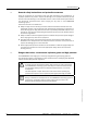
Important Information 1.3 Safety instructions 1.3.1 Intended use of the equipment The FLOWSIC600 measuring system is used for measuring the actual volumetric flow rate of gases transported in pipelines. It can be used for measuring the actual corrected volume and the speed of sound in gases. The measuring system shall only be used as specified by the manufacturer and as set forth below.
Important Information 1. 5 General safety instructions and protective measures Using the equipment for any purpose other than that intended by the manufacturer, or improper operation may result in injuries and damage to the equipment. Read this section and the notes and warnings in the individual sections of this manual carefully and observe the instructions contained therein when carrying out any work on the FLOWSIC600 measuring system.
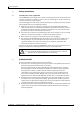
Important Information 1.7 Dangers due to heavy loads The FLOWSIC600 measuring system must be safely attached to the carrying structure when being transported and installed. WARNING: ● Only use lifting gear and equipment (e.g. lifting straps) which is suitable for the weight to be lifted. Max. load information can be found on the type plate of the lifting gear. ● The eye bolts attached to the meter body are suitable for the transport of the measuring device. However, additional loads (e.g.
Subject to change without notice Important Information 12 FLOWSIC600 · Operating Instructions · 8010125 V 4.
Product Description FLOWSIC600 2 Product Description Subject to change without notice System components Operating states, meter states and signal output Self-Diagnosis with User Warnings Data Handling in the FLOWSIC600 MEPAFLOW600 CBM FLOWSIC600 · Operating Instructions · 8010125 V 4.
Product Description 2. 1 System components The FLOWSIC600 measuring system consists of the following hardware components: ● Meter body ● Ultrasonic transducers ● Signal processing unit (SCU) The MEPAFLOW600 CBM software is the user interface used to facilitate configuration and diagnosis ( pg. 25, 2.5).
Product Description 2.1.2 Ultrasonic transducers The FLOWSIC600 ultrasonic transducers are optimized to suit your application requirements. The high quality of the transducer design provides the basis for accurate and highly stable propagation time measurements with nanosecond precision. These transducers are of an intrinsically safe design ("ia", with Equipment Protection Level Ga). 2.1.
Product Description 2. 2 Operating modes, meter states and signal output The FLOWSIC600 has two operating modes ( pg. 16, 2.2.1): ● Operation ● Configuration Mode In Operation Mode, the meter can have the following meter states ( pg. 17, 2.2.2): ● Measurement valid ● Chck request ● Data invalid 2.2.1 Operation mode and configuration mode The meter can be operated by the user in two modes: Operation Mode or Configuration Mode.
Product Description Meter states 2.2.2.1 Status: Measurement valid The meter status "Measurement" is the standard meter status of the FLOWSIC600. Frequency outputs and current output are updated cyclically and indicate the actual volume and volume flow rate. In addition, the analog signal can indicate the actual flow rate, corrected volumetric flow rate, SOS (speed of sound) or VOG (velocity of gas).
Product Description 2.2.3 Output of pulse signals and status information NOTICE: TYPE APPROVAL Pulse output signals can be customized as shown in the following table.
Product Description Table 2 Status output Output signal / LCD / port "Check request" Status signal "Direction of flow" Status signal "Warning" LCD display Serial port RS485 Signal behavior Measurement status Check request status Status Status "active / inactive" * "active / inactive" * Compensation of Measurement valid path failure Status Status "active / inactive" * "active / inactive" * Positive or negative Positive or negative direction of flow direction of flow Status Status "active / inactive" *
Product Description 2. 3 Self-diagnosis with User Warnings During normal operation, the ratios of sound and path velocities, amplification values, performance, and signal-to-noise ratios are continuously monitored. If these values exceed set limits (customized User Warning limits), a warning signal will be generated. This allows immediate measures to be taken to address a problem which could potentially impact measurement quality.
Product Description 2.4 Data handling in the FLOWSIC600 2.4.1 Integrated volume counters The FLOWSIC600 is equipped with integrated volume counters which can be displayed both on the LCD display and in MEPAFLOW600 CBM.
Product Description 2.4.2 Logbooks Important system events are stored in three logbooks in the SPU memory of the meter. Each logbook entry consists of a running index number, the event, a time stamp and the acknowledgement status. Entries in Custody logbook [1] and Warning logbook [2] also include the volume counter readings valid at that time. The events are logged continuously in order of occurrence into one of the three logbooks: ● Logbook 1 (Custody logbook [1], max.
Product Description 2.4.3 DataLogs1 For firmware version 3.4.03 and higher, the FLOWSIC600 provides two DataLogs (Hourly Log and Daily Log). They save averaged measured values and are stored in the SPU‘s nonvolatile memory (FRAM). All data can be downloaded and exported to Excel files with MEPAFLOW600 CBM ( pg. 97, 5.4.2.1.). The following sections describe the default configuration of the DataLogs. The DataLogs can be configured to best suit your application pg. 75, 4.7.2.2. 2.4.3.
Product Description 2.4.4 Diagnostics Comparison Log1 The Diagnostics Comparison Log provides a comparison between current diagnostic values (current fingerprint) and those of a reference time (reference fingerprint, for example, at time of commissioning). Since the diagnostic values (dataset type "Diagnostic Values", see Technical Information Table 11) are velocity-dependent, it is necessary to use a velocity-adaptive comparison.
Product Description 2.5 MEPAFLOW600 CBM Most data provided by the FLOWSIC600 (like readings, logbook entries and parameters) can be accessed via the LCD display of the meter. However, the MEPAFLOW600 CBM software provides a more user friendly access to diagnostic, configuration and measurement data of the flow meter.Software installation 2.5.1 System requirements ● ● ● ● ● Microsoft Windows XP/Windows 7 Min. 1 GHz CPU Min. 512 MB RAM USB- or serial interface Screen resolution min.
Product Description 2.5.2 Overview The MEPAFLOW600 CBM software supplies a menu-based user interface with many features for the diagnosis of the FLOWSIC600 system. It allows the access to all system parameters, displays diagnostic information in charts and graphs, generates reports (i.e. Maintenance reports) and data files (records, logs) which can be exported and can be used for data analysis.
Product Description Software features Main readings bar Meter Status User Warnings Key navigation Connect/Disconnect Diagnosis Session Data recorder DataLogs Meter logbook Information Meter values Maintenance report Meter explorer Go to Operation Mode / Go to Configuration Mode Program settings Parameters Save cache SOS Calculator Meter calibration Field setup Firmware update I/O check Path diagnosis Subject to change without notice Report manager Description Window displaying the current Meter Status.
Subject to change without notice Product Description 28 FLOWSIC600 · Operating Instructions · 8010125 V 4.
Installation FLOWSIC600 3 Installation Subject to change without notice General notes Installation Mechanical installation Electrical installation FLOWSIC600 · Operating Instructions · 8010125 V 4.
Installation 3. 1 General notes 3.1.1 Delivery The FLOWSIC600 is delivered in a pre-assembled condition in a sturdy package. When unpacking the device, check for possible damage in transit. Pay particular attention to the interior of the meter body, any visible transducer components and the sealing surfaces on the flanges. Any damage must be documented and reported to the manufacturer immediately. Also check the shipment to ensure all components are included.
Installation 3.1.2 Transport and storage WARNING: Only use lifting gear and equipment (e.g. lifting straps) which is suitable for the weight to be lifted. Max. load information can be found on the type plate of the lifting gear. It is strongly recommended to use only the eye bolts when lifting the meter by itself. To lift the FLOWSIC600 please pay attention to Figure 7.
Installation 3. 2 Installation Generally, the installation arrangement is specified during the project planning phase, before installation of the system. Nominal size, material and type of flange should therefore be in accordance with the design of the measurement facility. It is particularly important that the meter inlet and outlet is of the same internal diameter as the adjacent piping.
Installation 3.2.2 Installation configurations The choice of the installation configuration (see Figure 8 and Figure 9) depends on type and extent of the flow disturbance at the installation position.
Installation Bidirectional use Two straight pipes are to be installed in the inlet and outlet sections if the meter is to be used bidirectionally. The temperature measuring point is to be located downstream of the FLOWSIC600, seen in the direction of predominant use. The temperature measuring point must not be installed more than 8 DN from the meter. Figure 9 FLOWSIC600 installation in the pipeline for bidirectional use 10 DN 5 ..8 DN FLOWSIC600 5 ..
Installation 3.3 Mechanical installation Work on the pipelines to prepare for the installation of the gas flow meter is not included in the scope of delivery. It is recommended to use the following tools, equipment and supplies for installation of the FLOWSIC600: ● Lifting gear or fork lift (with sufficient capacity to lift meter or meter-piping assembly) ● Box wrench with size suitable for flange installation ● Thread seal (e.g.
Installation 3.3.2 Mounting the FLOWSIC600 in the piping An arrow on the meter body indicates the main direction of flow. It is recommended to install the FLOWSIC600 as indicated by this arrow if the meter is to be used for unidirectional flow applications. If the meter is to be used in the bidirectional mode, the arrow indicates the positive direction of flow. Installation work to be carried out WARNING: ● The lifting eyes are designed for transporting the meter only.
Installation 3.3.3 SPU alignment The signal processing unit (SPU) can be turned so that the display can be easily read and that cable routing is facilitated (see Figure 10). A stop on the housing prevents the SPU from being turned by more than 330° to prevent damage to the cables that come from the meter body. Figure 10 Positioning the SPU. Signal processing unit 1. 2. 3.
Installation 3. 4 Electrical installation 3.4.1 General information Prerequisites Wiring work (routing and connecting the power supply and signal cables), which is necessary when installing the FLOWSIC600, is not included in the scope of delivery. The mechanical installation described in Section 3.3 must be completed first. Comply with the minimum cable specification requirements set out in Section 3.4.2.
Installation General connection of the FLOWSIC600 Figure 11 FLOWSIC600 connection diagram Gas Volume at base conditions Electronic Volume Corrector (EVC) / Flow Computer (FC) Compressibility factor Z Heating value Hs Gas volume at flowing conditions Pressure Energy content Temperature RS485 / MODBUS Service PC / higherlevel control system (Ex i isolating transformer only required for intrinsically safe installation) 12 ...
Installation 3.4.2 Cable specifications WARNING: The cables must - fulfil the requirements for use in hazardous areas (e.g. set forth in EN /IEC 60079-14 or other relevant standards). Power supply 12 … 28.8 V DC Specification Notes Type of cable Two conductors Connect shielding (if present) to ground terminal Min./ max. cross-sectional area 0.5 mm² / 2.5 mm² (20 - 12 AWG) Maximum cable length Depending on loop resistance; Minimum input voltage on the FLOWSIC600 must be 12 V DC.
Installation 3.4.3 Checking the cable loops Check the cable loops to verify that the cables are connected correctly. Proceed as follows: Disconnect both ends of the cable of the loop to be tested. This is to prevent connected devices from interfering with the measurement. Test the entire cable loop between SPU and terminal device by measuring the loop resistance.
Installation 3.4.4 Terminal enclosure on the SPU Opening the rear housing cover Loosen the securing clip using a 3 mm Allen key. Turn the rear housing cover counter-clockwise and take it off. NOTICE: Lubricant Only use LOCTITE 8156 as lubricant for front and rear housing cover. A schematic wiring diagram is provided on the inside of the rear housing cover. Figure 12 SPU housing Open the cover Window cover Rear cover Securing clip Terminal box on the rear of the SPU (see Section 3.4.
Installation Figure 14 Terminal assignment for use in safe areas Terminal box Power supply Field connections (10-pole terminal block) PE PE NOTICE: Potential equalization PE: Potential Equalization terminal must be connected to earth ground. NOTICE: Device-internal bridge Terminals 2 and PE are bridged internally, i.e. there is no insulation between PE and negative potential ( Figure 13). This bridge is a firm part of the device and mandatory. It must not be removed or altered.
Installation 3.4.5 Operating the FLOWSIC600 in non-hazardous areas Assign the terminals in the SPU terminal box ( Figure 14) in accordance with the following table. 1 Connection for Function Power supply Termina Value l 1+, 212 ... 24 (+20%) V DC fmax = 6 kHz, configurable pulse duration 0.05 s 1s Range: Variable number of pulses per volume unit 31, 32 "closed": 0 V UCE L 2 V, 2 mA ICE L 20 mA (L=Low) "open": 16 V UCE H 30 V, 0 mA ICE H 0.
Installation 3.4.6 Requirements for use in hazardous areas with potentially explosive atmospheres1 Intended use The FLOWSIC600 is suitable for use in hazardous areas classified as Zone 1 and Zone 2. Certification in accordance with ATEX II 1/2 G Ex de ib [ia] IIC T4 II 1/2 G Ex de ib [ia] IIA T4 Permitted ambient temperature range -40°C to +60°C EC TYPE Examination Certificate: TÜV 01 ATEX 1766, include 1. to 6.
Installation Operating conditions for the ultrasonic transducers The FLOWSIC600 is designed for use in hazardous areas with potentially explosive atmospheres only under normal atmospheric conditions. The atmospheric conditions must be within the following ranges: – Ambient pressure range 80 kPa (0.8 bar) to 110 kPa (1.1 bar) – Air with normal oxygen content, typically 21% v/v The ambient temperature must be within the range specified at the SPU type plate, e.g -40°C to +60°C.
Installation Additional requirements for operation of ultrasonic transducer in Zone 0 classified areas The FLOWSIC600 is marked with a minimum rating of II 1/2 G Ex [ia] or Gb/Ga Ex [ia Ga]. Operation of ultrasonic sensors in Zone 0 The ultrasonic transducers are suitable for operation in Zone 0 at atmospheric conditions, i.e. ambient temperature -20 °C to 60 °C and ambient pressure 0.8 bar to 1.1 bar(a).
Installation Requirements regarding cabling – Cables must fulfill the requirements set forth in EN/IEC60079-14. – Cables that are subject to exceptional thermal, mechanical or chemical stress must be specially protected, e.g. by laying them in protective tubing. – Cables that are not installed fire proof must be flame retardant according to IEC 60332-1. – Cables for Ex e must comply with EN/IEC 60079-14 section 11. – Observe the clamping range of the cable glands for cable selection.
Installation Connection of the FLOWSIC600 with associated equipment The terminal compartment of the FLOWSIC600 complies with the requirements of EN/ IEC60079-7 and EN/IEC 60079-11, respectively.
Installation Terminal assignment The terminal assignment in the SPU terminal box (see pg. 43, Figure 14) is the same as for the installation of the FLOWSIC600 in non-hazardous areas (see table pg. 44, 3.4.5). NOTICE: For measurement reasons, the equipotential bonding must, as far as possible, be identical to the pipeline potential or protective ground/earth.
Installation Notes for safe operation in hazardous areas WARNING: Always observe the temperature specifications for use in hazardous areas. Approval of the ultrasonic transducers in zone 0 is only valid for operation under atmospheric conditions. ● Explosion protection: II 1/2G Ex de ib [ia] IIC T4 or II 2G Ex de ib [ia] IIA T4 ● Ambient temperature range is from -40°C to +60°C.
Installation Safety-relevant data of inputs and outputs for ATEX certified FLOWSIC600 only Power circuit Intrinsically safe Ex ia/ib IIA/IIB/ IIC Power supply Active current output Terminals 31/32 UI = 20 V, PI = 2,6 W UO = 22.1V IO PO [mA] [mW] Ex ia/ib IIA CO [μF] LO [mH] Ex ia/ib IIB CO [μF] LO [mH] Ex ia/ib IIC CO [nF] LO [mH] Nonintrinsically safe 12...
Installation Safety-relevant data of inputs and outputs for IECEx certified FLOWSIC600 only Power circuit Intrinsically safe Ex ia/ib IIA/IIB/ IIC Power supply Active current output Terminals 31/32 UI = 20 V, PI = 2,6 W UO = 22.1V IO PO Ex ia/ib IIA Ex ia/ib IIB Ex ia/ib IIC [mA] [mW] CO [μF] LO [mH] CO [μF] LO [mH] CO [nF] LO [mH] All hardware variants 87 481 2 7 0.
Subject to change without notice Installation 54 FLOWSIC600 · Operating Instructions · 8010125 V 4.
Commissioning FLOWSIC600 4 Commissioning Subject to change without notice General notes Connecting the FLOWSIC600 to a PC or laptop Connecting to the FLOWSIC600 with MEPAFLOW600 CBM Identification Field setup Function test Activation of path compensation Sealing Documentation FLOWSIC600 · Operating Instructions · 8010125 V 4.
Commissioning 4. 1 General notes Before commissioning, all activities described in the chapter »Installation« must be completed. It is recommended to use a laptop/PC with MEPAFLOW600 CBM software installed for the commissioning ( pg. 59, 4.3). The commissioning should be documented with a Commissioning Protocol. The document "FLOWSIC600 Commissioning Protocol" is content of the FLOWSIC600 shipping on paper and on the product CD.
Commissioning 4.2 Connecting the FLOWSIC600 to a PC or laptop 4.2.1 Connecting the FLOWSIC600 via RS485 / RS232 cable Interface sets for the connection of the FLOWSIC600 with a PC via serial or USB-interface can be ordered from SICK. See pg. 58, Table 3. The FLOWSIC600 serial interface conforms with the RS485 standard. An RS485 /RS232 cable and a 1:1 interface cable (pin 2 – pin 2 and pin 3 – pin 3) are required for data transfer to PC or laptop (see Figure 17).
Commissioning 4.2.2 Connecting the FLOWSIC600 via RS485/USB converter If the PC/laptop does not offer a RS232 serial interface, a USB interface can be used. An appropriate USB converter is necessary to transform the signal for the RS485 device interface. The USB converter available through SICK contains a CD-ROM with a software driver which must be installed before an online connection between the FLOWSIC600 and the MEPAFLOW600 CBM software can be established.
Commissioning 4.3 Connecting to the FLOWSIC600 with MEPAFLOW600 CBM 4.3.1 Starting MEPAFLOW600 CBM The MEPAFLOW600 CBM software is provided on the product CD shipped with the meter. It can also be downloaded from www.flowsic600.com. See pg. 25, for more details on the installation. After successful installation, start the MEPAFLOW600 CBM by selecting the "MEPAFLOW600 CBM" entry in the program group "SICK", created during installation, or by double-clicking on the desktop icon. 4.3.
Commissioning Figure 19 MEPAFLOW600 CBM "Connect / Disconnect" page with "Password" dialog window 4.3.3 Creating a new meter entry in the meter database New meter entries can be created, whether the corresponding meter is connected to the PC or not. If the meter is connected, MEPAFLOW600 CBM loads all available parameters from the meter. If the meter is not connected, an initial master data set is created from the information the user enters (see Technical Data).
Commissioning 4.3.4 Online connection: Direct serial Choose a meter and click the "Direct serial" button to establish a serial connection to a meter which is connected to the PC ( Figure 20). Specify the appropriate connection settings in the "Connection settings" window ( Figure 20) and click the "Connect" button to establish an online connection to the meter. If the connection fails, see pg. 108, 6.4 for troubleshooting.
Commissioning Edit the fields for the meter identification in the "Add new meter into database" dialog. The serial number, firmware version and meter type are automatically read from the meter Figure 21. After the connection has been established, MEPAFLOW600 CBM displays the start page (can be specified in the Program settings) and the current readings from the meter. Adding new meter to database Subject to change without notice Figure 21 62 FLOWSIC600 · Operating Instructions · 8010125 V 4.
Commissioning 4.3.5 Online connection: Ethernet The FLOWSIC600 can be connected to a network via Ethernet with an adapter. This adapter translates the meter MODBUS communication (ASCII or RTU) to MODBUS TCP. MEPAFLOW600 CBM supports the MODBUS TCP protocol. Requirements ● The Ethernet connection requires firmware V3.3.05 or higher. It provides the required generic MODBUS protocol on the interface for the MODBUS TCP adapter.
Commissioning Figure 22 "MODBUS TCP - MODBUS RTU/ASCII gateway settings" dialog for online connections via Ethernet MODBUS TCP - MODBUS RTU/ ASCII gateway settings Button for Ethernet connections Tested MODBUS TCP to MODBUS ASCII/RTU adapter The connection between FLOWSIC600 and MEPAFLOW600 CBM has been tested with the "MODBUS TCP to MODBUS ASCII/RTU Converter", Model MES1b by B&B Electronics.
Commissioning 4.4 Identification 4.4.1 Checking identification, operation / design data and firmware version Before commissioning, cross-check the data representing the flow meter with the data in the test protocols which are contained in the Manufacturer Data Report (MDR).
Commissioning 4.4.1.1 Firmware The FLOWSIC600 firmware is stored on a non-volatile memory (FLASH PROM). The program code for the signal processor and system micro-controller are identified by a version number (Reg. #5002 "FirmwareVersion") and a check sum (Reg. #5005 "ProgramCRC") and can be verified as mentioned above.
Commissioning Field setup 4.5 The MEPAFLOW600 CBM software "Field setup" wizard guides the user through the parameter configuration during the commissioning of the FLOWSIC600. The wizard consists of 8 pages. For checking the configuration of the SPU outputs refer to the "Instrument Data Sheet" of the FLOWSIC600, which is included in the Manufacturer Data Record (MDR) (example see Figure 24).
Commissioning 4.5.1 Disconnecting from the meter and closing the session When disconnecting from the meter, a session is stored in the MEPAFLOW600 CBM meter database.
Commissioning 4.6 Function test The major system parameters are configured at the factory. The default settings should allow error free operation of the FLOWSIC600. Nevertheless, correct meter operation should be verified on site when the meter is installed and is subject to actual operating conditions. 4.6.
Commissioning 4.6.3 Function test with MEPAFLOW600 CBM Performance check Once the facility is flowing at the initial flow rate, go to the "Meter values" page to check the performance of the meter. The performance value should be at least 75% on all paths. If the velocity of gas is greater than 30 m/s (100 ft/s), the performance values may be significantly lower.
Commissioning In addition, the validity of the settings should be verified: Open the "Meter status" window and go to the tab "Advanced or Path Status" ( pg. 83, Figure 30). If a lamp for "Time plausibility" is on, it indicates an incorrect zero phase. Figure 26 Signal window displaying ultrasonic signal in the "Path Diagnosis" page Go to the "Meter values" page to check that the measured SOS values are almost the same at all paths of the FLOWSIC600, and that they differ by less then 0.
Commissioning 4. 7 Optional advanced setup 4.7.1 Configuration and activation of User Warnings When normal operating conditions have been reached, the User Warnings can be configured to best suit the specific application. ● The User Warnings are preconfigured when the meter is shipped from the factory (see "Default activation state" and "Default value" see Technical Informationin the following tables pg. 151, Table 20).
Commissioning Button "User" in the main system bar, "User Warnings" assistant with "Status" and "Configuration" tab "User" Button "Configuration" tab Subject to change without notice "Status" tab FLOWSIC600 · Operating Instructions · 8010125 V 4.
Commissioning 4.7.2 Configuration of DataLogs 4.7.2.1 Using the DataLogs Starting with firmware version 3.4.00, the FLOWSIC600 provides two DataLogs (Hourly Log and Daily Log). They save averaged measured values and are stored in the SPU‘s nonvolatile memory (FRAM). All data can be downloaded and exported to Excel files with MEPAFLOW600 CBM ( pg. 24, 2.4.4.).
Commissioning 4.7.2.2 Configuration of DataLogs The following parameters can be configured on the Configuration tab of the DataLogs page ( Figure 28) to best suit the specific application (for more details see pg. 23, 2.4.3.4 and following): ● Type of dataset, ● Storage cycle, ● Storage behavior, ● Active flow direction, ● Accounting hour ● Distribution of FRAM capacity.
Commissioning Complete the following steps to configure the DataLogs: Go to the DataLogs page (select Meter / DataLogs from menu). Choose the Configuration tab (see Figure 28). Switch the meter into Configuration Mode (choose "File / Configuration Mode" from the menu). Use the drop down lists to select the parameter settings. Click the "Write to meter" button. Figure 28 DataLogs Configuration tab 4.7.2.
Commissioning 4.7.2.4 Enabling (starting) DataLogs To enable (start) a disabled DataLog, complete the steps described under pg. 77, 4.7.2.5 (Resetting DataLog Parameters to Defaults). 4.7.2.5 Resetting DataLog parameters to defaults Before resetting DataLog Parameters to Defaults In MEPAFLOW600 CBM from V1.1.00, DataLog entries are not saved in the meter database. Before clearing entries from DataLogs, download and export the entries into Excel ( pg. 96, 5.4.2).
Commissioning 4.7.3 Configuring and using the Diagnostics Comparison Log The Diagnostics Comparison Log can be used to get information on changes in the meter‘s health (more information pg. 24, 2.4.4): The Diagnostic Comparison Report, created from the data of the Diagnostics Comparison Log, facilitates an easy and quick information about changes in the meter health between two different points of time (e.g. commissioning and now) (see Technical Information Diagnostic Comparison Report Check). 4.7.3.
Commissioning When the reference classes are filled with data representing the usual operation of the installation, the current classes will be continuously updated, showing the current state of the meter. Use the Diagnostics Comparison Report (see Technical Information) pg. 181, 6.4.3, to detect changes in the meter between the diagnostic values in the reference classes and those in the current classes. 4.7.3.
Commissioning 4.7.3.4 Configuration of the Diagnostics Comparison limits The Diagnostics Comparison limits can be activated to make the meter generate a warning when the difference between the diagnostic values in the reference classes and those in the current classes exceed the Diagnostics Comparison limit values. These limits can be activated and configured in the User Warnings window: Use MEPAFLOW600 CBM to connect to the meter ( pg. 59, 4.3).
Commissioning Table 6 Diagnostics Comparison limits Monitored difference between reference Configurable Default values and current difference limit value values Profile factor Profile Factor 10% change Symmetry Symmetry change SOS differences between paths SOS difference 1% change Turbulence Turbulence change 50% SNR (Signal-to-noise ratio) SNR change 20dB AGC (Signal amplification) AGC change 10dB Default activation state1 A change of the profile factor value may be caused by contamination
Commissioning Figure 29 "User Warnings" window with "Diagnostics Comparison limit" tab Subject to change without notice "User" Button 82 FLOWSIC600 · Operating Instructions · 8010125 V 4.
Commissioning 4.8 Activation of path compensation If the status bit "Path compensation valid" is "active", then the FLOWSIC600 is able to compensate a path failure. The meter automatically sets this bit to "active" after operating for about 20 minutes with error free measurement at all paths at a gas velocity between 1 to 8m/s (3.3 to 26.2 ft/s) and also about 20 minutes at a gas velocity higher than 8m/s (26.2 ft/s). The status bit "Path compensation valid" is displayed on the "Meter status" page ( pg.
Commissioning 4. 9 Sealing After having completed the commissioning, seal the signal processing unit (if required) in accordance with the sealing plan ( pg. 132, 7.6). 4. 1 0 Documentation Subject to change without notice The commissioning should be documented with a Commissioning Protocol. The document "FLOWSIC600 Commissioning Protocol" is content of the FLOWSIC600 shipping on paper and on the product CD.
Maintenance FLOWSIC600 5 Maintenance Subject to change without notice General Routine checks Maintenance report Optional data download FLOWSIC600 · Operating Instructions · 8010125 V 4.
Maintenance 5. 1 General The FLOWSIC600 does not contain mechanically moving parts. The meter body and ultrasonic transducers are the only components that come into contact with the gaseous media. Titanium and high-quality stainless steel ensure that these components are resistant to corrosion, provided that the meter is installed and operated in accordance with the relevant specifications. This means that the FLOWSIC600 is a low-maintenance system.
Maintenance 5.2 Routine checks The information displayed on the front panel LCD display of the FLOWSIC600 meter can be checked to ensure that the system is functioning properly. The MEPAFLOW600 CBM software provides a more user friendly way for doing routine checks. 5.2.
Maintenance Enter the gas composition and specify temperature and pressure for your specific application. Click the "Calculate" button. If the SOS calculator was started from the Maintenance Report, the calculated value is automatically copied to the corresponding field in the wizard and to the report. Compare the theoretical SOS with the SOS measured by the FLOWSIC600 (see Figure 32, main system bar). The deviation between both should be less than 0.1%. If the deviation exceeds 0.
Maintenance 5.2.2 Checking the meter health The FLOWSIC600 monitors its own meter health with User Warnings and system alarms. If the outputs are configured to indicate alarms and / or User Warnings, it is not necessary to manually check the meter health. To get visual feedback about the meter‘s health, the "Main system bar" in MEPAFLOW600 CBM provides a compact overview: Use MEPAFLOW600 CBM to connect to the meter ( pg. 59, 4.3). Check the main system bar for any yellow or red icon ( Figure 32).
Maintenance 5.2.3 Time synchronization All entries in logbooks or datalogs saved in the meter‘s memory (FRAM) are written with a time stamp containing the meter time. The meter time can be synchronized with a master clock (e.g. PC clock) via MODBUS or with MEPAFLOW600 CBM. A synchronization causes a logbook entry in the Custody logbook [1] only if the time change is greater than 3% of the time elapsed since the last synchronization.
Maintenance 5.2.4 Battery lifespan / capacity The Real Time Clock (RTC) of the FLOWSIC600 is buffered by a battery. The manufacturer states that the battery life span is at least ten years. The remaining battery capacity can be viewed on the LCD in the first menu level (see Technical Information).
Maintenance 5. 3 Maintenance report It is recommended that Maintenance Reports be generated and filed on a regular basis. This creates a basis of comparable data over time and helps when a problem has to be diagnosed. The operating conditions (gas composition, pressure, temperature, flow velocity) of the individual Maintenance Reports should be similar or documented separately and taken into account when the data is analyzed.
Maintenance Specify the "Collection duration", a timespan, over which live meter data is to be collected to document the meter‘s state (default: 1 minute). Enter the current pressure, temperature and SOS. Use the SOS Calculator to calculate the SOS for the gas composition ( pg. 87, 5.2.1). The gas composition must be current and representative. Click the "Start" button to start live data collection.
Maintenance 5. 4 Optional data download 5.4.1 Logbook check To prevent an overflow of the logbooks and possible data loss, logbook entries can be saved to the meter database with the MEPAFLOW600 CMB software. The entries on the meter can then be deleted. 94 Figure 36 "Meter logbook" page in MEPAFLOW600 CBM 5.4.1.
Maintenance 5.4.1.2 Acknowledging logbook entries on the meter To acknowledge logbook entries on the meter, proceed as follows: Download and save the logbook entries from the meter according to 5.4.1.1. Select the logbook in which entries are to be acknowledged or select "All logbooks" to acknowledge entries in all logbooks at once. Mark the entries to be acknowledged.
Maintenance 5.4.2 DataLogs check Starting with firmware version 3.4.00, the FLOWSIC600 provides two DataLogs (Hourly Log and Daily Log). They save averaged measured values and are stored in the SPU‘s nonvolatile memory (FRAM). All data can be downloaded and exported to Excel files with MEPAFLOW600 CBM ( pg. 73, on configuring the DataLogs.). Full support for the DataLogs is provided by MEPAFLOW600 CBM V1.1.00 or higher.
Maintenance 5.4.2.1 Downloading and exporting of DataLog data To download and export the data from your FLOWSIC600, complete the following steps: Use MEPAFLOW600 CBM to connect to the meter ( pg. 59, 4.3). Go to the DataLogs page (choose "Meter / DataLogs" from the menu). In the dialog "DataLog selection", select those DataLogs that you want to view and/or export and click "OK". Now the DataLogs page is displayed with the data from the meter (see Technical Information).
Maintenance Subject to change without notice To clear all entries from a DataLog, complete the following steps: Go to the DataLogs page (select Meter / DataLogs from menu). Choose the Configuration tab. Switch the meter into Configuration Mode (choose "File / Configuration Mode" from the menu). Click the "Clear" button for the DataLogs from which you want to clear entries. Switch the meter into Operation Mode. 98 FLOWSIC600 · Operating Instructions · 8010125 V 4.
Troubleshooting FLOWSIC600 6 Troubleshooting Subject to change without notice General troubleshooting Indication of meter states, system alarms and warnings Generation of diagnosis session Meter connection troubleshooting FLOWSIC600 · Operating Instructions · 8010125 V 4.
Troubleshooting This chapter provides solutions for problems highlighted by routine tests during maintenance ( pg. 87, 5.2) or the function tests after commissioning ( pg. 69, 4.6). If the cause of the problem cannot be localized, it is recommended to use the MEPAFLOW600 CBM software to record the current parameter set and diagnosis values in a diagnosis session file ( pg. 107, 6.3) and send this to a local SICK representative. 6.
Troubleshooting 6.2.1 Checking the "Meter Status" window The "Meter status" window in MEPAFLOW600 CBM displays an overview about the meter's status and operation. Use MEPAFLOW600 CBM to connect to the meter ( pg. 59, 4.3). Click on the "System" button in the main system bar to open the "Meter status" window ( Figure 38). Check the general "Meter Status" section (marked in Figure 38) for yellow or red lights.
Troubleshooting Figure 38 Main system bar with "System" button and opened "Meter Status" window Opens the "Meter Status" window Main system bar General "Meter Status" section Indication if logbook(s) contain(s) unacknowledged entries "DataLogs" section Subject to change without notice Battery change "Logbooks" section 102 FLOWSIC600 · Operating Instructions · 8010125 V 4.
Troubleshooting 6.2.2 Checking the "User Warnings" window The "User Warnings" window displays an overview about the User Warning status. Use MEPAFLOW600 CBM to connect to the meter ( pg. 59, 4.3). Click on the "User" button in the main system bar of the MEPAFLOW600 CBM screen to open the "User Warnings" window ( Figure 39). Check the window for yellow lights and proceed according to Technical Information.
Troubleshooting 6.2.3 Checking the diagnostic meter values The "Meter values" page displays detailed diagnostic information: Use MEPAFLOW600 CBM to connect to the meter ( pg. 59, 4.3). Choose "Meter / Meter values" from the menu to call up the "Meter values" page ( Figure 40). Check the "Meter values" page for any yellow or red graphs or yellow or red indicators in the Main system bar. Yellow or red indicates a potential problem.
Troubleshooting Problem Implausible sepeed of sound Possible causes Gas composition, pressure or temperature measurement is incorrect Different speed of sound Faulty transducer or in the individual paths electronic module Lower signal-to-noise ratio and reception sensitivity Increased number of rejected measurements in individual paths Increased receiver sensitivity (AGC) Create a Diagnosis Session according to pg. 107, 6.3 and contact your trained staff or your local SICK representative.
Troubleshooting 6.2.4 Battery lifespan / capacity Because the FLOWSIC600 has no regular maintenance cycle, a user warning will be automatically generated if the remaining battery life is less than 15%. After 8.5 years, a warning is generated which forces the operator to change the battery. The battery may only be changed by trained staff. The procedure for changing the battery is described in the Service Manual. For further information on warning settings see Technical Information.
Troubleshooting 6.3 Generation of a Diagnosis session If it becomes necessary to generate a Diagnosis session for remote support, follow the procedure described below: Start the MEPAFLOW600 CBM software and establish an online connection to the meter (see pg. 59, 4.3 for all necessary preparations).
Troubleshooting 6. 4 Meter connection troubleshooting Meter not found at initial connection/connection lost during session Check all cables and the hardware. Check also the correct installation of the adapters (see pg. 57, 4.2.1 and pg. 58, 4.2.2). Attempt to re-establish connection via "Connect to Meter" window. Use the options in the window displayed to make MEPAFLOW600 CBM search with wider options ( Figure 44), especially if parameters (e.g. the baud rate) may have been changed.
Appendix FLOWSIC600 7 Appendix Subject to change without notice Conformities and technical data Logbooks Connection diagrams for operating the FLOWSIC600 in hazardous areas in accordance with North American Guidelines (NEC, CEC) Wiring examples Sealing plan FLOWSIC600 · Operating Instructions · 8010125 V 4.
Appendix 7. 1 Conformities and technical data 7.1.1 CE certificate The FLOWSIC600 has been developed, manufactured and tested in accordance with the following EC directives: ● Pressure Equipment Directive 97/23/EC ● Directive 94/9/EC (ATEX) ● EMC Directive 2004/108/EC ● MID Directive 2004/22/EC Conformity with above directives has been verified and the device has been marked with the CE label.
Appendix Figure 45 Common key code (for short description of meter design, indicated on Type Plate* and Instrument Data Sheet**) Type Code FLOWSIC600 Group 1 Key code 1 2 3 4 5 6 7 8 10 SIGNAL PROCESSING UNIT Subject to change without notice 13 14 15 4 5 7 6 8 10 9 - Path configuration 1-Path 1 P 2-Path 2 P 4-Path 4 P 1+1-Path redundant 1 R 2+2-Path redundant 2 R 4+4-Path (Quatro) 4 R 4+1-Path (2plex) 5 C 2-Path crossed 2 X 4-Path crossed 4 X 2-Path Special 2 S Overall length 2D 2
Appendix 7.1.4 Technical data Type approval The information in this section may differ from the type approval which is valid for the FLOWSIC600 in your country. Please use your national type approval for the FLOWSIC600.
Appendix Subject to change without notice Table 9 Technical data Meter characteristics and measuring parameters Measured variables Flow rate, volume at flowing and base conditions, gas velocity, speed of sound Number of measuring paths 2, 4, 4+1, 4+4 Measuring Principle Ultrasonic transit time difference measurement Measured medium Natural gas, N2, O2, air, C2H4, vapor, process gases Measuring ranges Actual flow rate. 4 ... 400 m³/h / 1,600 ...
Appendix Outputs and interfaces Analog output Digital outputs Interfaces Bus protocol Operation Installation Dimensions (W x H x D) Weight Material in contact with media Electrical connection Voltage See dimension drawings Depending on device version Low-temperature carbon steel, stainless steel, Duplex steel 12 ... 28.8 V DDC For active current output: 15 ... 28.8 V DDC ≤1W The scope of delivery is dependent on the application and the customer specifications.
Appendix Criteria applicable to meter when used in accordance with metrological type approval Table 10 Meter sizes according to metrological type approval Meter size DN 80 (3") Measuring range (Qmin [m³/h]) Meter size 1:100 1:80 8 13 G1000 20 G1000E 32 20 32 28800 8 13 20 400 18000 13 20 32 650 11100 13 250 28800 13 20 400 18000 13 20 32 650 11100 20 32 50 1000 7200 20 400 18000 20 32 650 11100 20 32 50 1000 7200 32 50 80 1600 4500 2200 3272 130
Appendix DN 400 (16") Measuring range (Qmin [m³/h]) Meter size 1:100 G4000 G6500 E 120 1:30 1:20 G6500 130 200 4000 1800 130 200 320 6500 1110 200 320 500 10000 720 12000 600 130 200 320 6500 1110 200 320 500 10000 720 16000 450 130 G4000 G6500 G10000 200 200 320 6500 1110 200 320 500 10000 720 320 500 800 16000 450 20000 360 G10000 E 200 DN 550 (22") G6500 G10000 G16000 DN 600 (24") 200 200 320 500 10000 720 320 500 800 16000 450 25000
Appendix Meter size DN950 (38“) Measuring range (Qmin [m³/h]) Meter size 1:100 1:80 1:50 1:30 G16000 1300 G25000 1300 G40000 800 1300 DN 1000 G16000 (40") G25000 G40000 1:20 1300 1300 650 800 1300 Max. flow rate Qmax [m³/h] Meter factor [pulses/ m³] 25000 288 40000 180 65000 111 25000 288 40000 180 65000 111 ● Any flow rates given above are also valid in the bidirectional mode. ● G-classes marked with an asterisk (*) must only be used in configuration No. 2 (see pg.
Appendix 7. 2 Logbooks 1 Classification of logbook entries The entries are distinguished into three classes and identified by the initial character in the first line. ● "I"information ● "W"warning ● "E"error/ malfunction 2 Type of occurrence ● "+"point of time identifying the beginning of a status ● "-"point of time identifying the end of a status 7.2.1 Overview of event entries in meter logbooks Message No.
Appendix Message No. Details on LCD 3009 3011 3012 3013 3014 CRC volume counter (a.c) invalid CRC volume counter (n.
Appendix Message No. Details on LCD Logbook LCD Text I+Meas.Mode 0001 Configurat. ON 1 1003 Configuration Mode active 1 1004 Firmware changed 1 I Update FW 0001 3104 -> 3200 1007 Custody logbook [1] erased and initialized 1 I Logbook 1 0001 Reset and Init 1014 Overflow volume counter (a.c.) 1 I Count.ac Overflow 0001 1015 Overflow volume counter (s.c.) 1 I Count.
Appendix Message No.
Appendix 7. 3 SPU terminal assignment Connection in accordance with ATEX IIA Figure 46 Terminal assignment in accordance with ATEX IIA 1(+) power supply alimentation UB = 12..24V DC 2 (-) EEx e Um=253V EEx ib [ia] IIA 31 32 33 34 4 ...
Appendix Connection in accordance with ATEX /IECEx IIA Figure 48 Terminal assignment in accordance with ATEX IIA power supply alimentation UB = 12..24V DC 1(+) 2 (-) Ex e Um=253V, Ex ia IIA 31 32 4 ...
A B C D 1 2 US-Transducer 1 US-Transducer SPU-LINK (Option only) Voc=12.3V Isc=130mA Ca=600nF Connector La=1mH Connector GND 2 2 (-) 31 32 33 34 51 52 41 42 81 82 1 (+) GND SPU-LINK (Option only) Voc=12.3V Isc=130mA Ca=600nF Connector La=1mH Connector Class I, Zone 1, Group II B + Hydrogene, Temp. Code T4 GND 31 32 33 34 51 52 41 42 81 82 GND 4 3 Sick Engineering GmbH Bergener Ring 27 01458 Ottendorf-Okrilla GERMANY 781.00.02 4 2.0 A4 von 6 18-Jul-2012 _ Rev.
FLOWSIC600 · Operating Instructions · 8010125 V 4.0 · © SICK AG A B C D 1 2 US-Transducer Voc=51.2V Isc=77mA Ca=18nF La=0.03mH 1 US-Transducer Up to 8 [Exia] Terminals for Ultrasonic Transducers manufactured by SICK only with the following Entity Parameters US-Transducer Class I, Zone 0, Group II B, Temp. Code T4 Voc=51.2V Isc=77mA Ca=18nF La=0.
FLOWSIC600 · Operating Instructions · 8010125 V 4.0 · © SICK AG US-Transducer Voc=60.8V Isc=92mA Ca=30nF La=0.03mH 1 US-Transducer Up to 8 [Exia] Terminals for Ultrasonic Transducers manufactured by SICK only with the following Entity Parameters US-Transducer Class I, Zone 0, Group IIA, Temp.
1(+) Entity Parameters Vmax=20V, Imax =200mA Ci = 4nF, Li = 0.075mH FLOWSIC600 · Operating Instructions · 8010125 V 4.0 · © SICK AG digital output 2 sortie digital 2 digital output 3 sortie digital 3 41 42 81 82 Voc=22,1V Vmax=30V Isc=155mA Imax=100mA Ca=77nF Ci=4nF La=1mH Li=0.075mH Vmax=30V Ci=4nF Imax=100mA Li=0.075mH Vmax=30V Imax=100mA Ci=4nF Li=0.075mH Vmax=30V Imax=100mA Ci=4nF Li=0.075mH Voc=5.88V Isc=313mA Ca=430nF La=0.2mH Vmax=10V Imax=275mA Ci=4nF Li=0.
2 (-) 1(+) Entity Parameters Vmax=20V, Imax =200mA Ci = 4nF, Li = 0.075mH 4 ...20 mA FLOWSIC600 · Operating Instructions · 8010125 V 4.0 · © SICK AG digital output 3 sortie digital 3 41 42 81 82 Subject to change without notice digital output 2 sortie digital 2 Voc=22,1V Vmax=30V Isc=155mA Imax=100mA Ca=500nF Ci=4nF La=4mH Li=0.075mH Vmax=30V Ci=4nF Imax=100mA Li=0.075mH Vmax=30V Imax=100mA Ci=4nF Li=0.075mH Vmax=30V Imax=100mA Ci=4nF Li=0.075mH FLOWSIC600 -x-x-C-0-x Ind. Änderung Voc=5.
1(+) Entity Parameters Vmax=20V, Imax =200mA Ci = 4nF, Li = 0.075mH FLOWSIC600 · Operating Instructions · 8010125 V 4.0 · © SICK AG digital output 3 sortie digital 3 41 42 81 82 Vmax=30V Ci=4nF Imax=100mA Li=0.075mH FLOWSIC600 -x-x-D-0-x Ind. Änderung Voc=5.88V Isc=313mA Ca=1μF La=2mH Vmax=10V Imax=275mA Ci=4nF Li=0.
1RQ +D]DUG $UHD FLOWSIC600 · Operating Instructions · 8010125 V 4.0 · © SICK AG 'DWXP 1DPH [ PPð 1<< 2 ([ 1 'DWXP %HDUE *HSU 1RUP Subject to change without notice =XVW bQGHUXQJ ([SORVLRQ +D]DUG /RFDWLRQ ([ [ [ PPð /L <&([ LD@ ,,& [ [ PPð /L <&
1RQ +D]DUG $UHD =XVW bQGHUXQJ ([SORVLRQ +D]DUG /RFDWLRQ 'DWXP 1DPH 1<< 2 [ PPð ; $ IDVW 'DWXP %HDUE *HSU 1RUP 5/ [ [ PPð /L <&
Side view, front 2* 2 2 1 Front view 2 * minimum of two seals per capping Placement of seals, capping - front and rear Side view, rear 1 Sealing plan, part 1 (cast version) 2 2 Figure 58 Placement of seals, SPU cover - front and rear 2 Sealing plan 1 1 7. 6 Subject to change without notice 2 1 Appendix FLOWSIC600 · Operating Instructions · 8010125 V 4.
1 1 Side view, front Side view, front 2 2 Detail X 1 2* Front view FLOWSIC600 · Operating Instructions · 8010125 V 4.
1 1 FLOWSIC600 · Operating Instructions · 8010125 V 4.
Appendix Figure 61 Sealing plan, part 4 alternatively 2 3 3 Subject to change without notice 1 FLOWSIC600 · Operating Instructions · 8010125 V 4.
Appendix Examples: Main type plates on the signal processing unit (right: including conformity label) SICK Engineering GmbH Bergener Ring 27 D-01458 Ottendorf-Okrilla SICK Engineering GmbH Bergener Ring 27 D-01458 Ottendorf-Okrilla FLOWSIC600 00 01 Part No. Serial No. Year FLOWSIC600 00 Part No. Serial No. Year 02 Approval Sign 03 01 0044 DE-08-MI002-PTB005 02 M xx 0102, 0044 03 Made in Germany 04 20 06 22 Q max 08 24 Q min 09 25 27 = 10 26 15 Variable UN = 12 ...
Subject to change without notice Appendix FLOWSIC600 · Operating Instructions · 8010125 V 4.
8010125/2014-09/V4.0/ISubject to change without notice AUSTRALIA Phone +61 3 9457 0600 1800 334 802 – tollfree E-Mail sales@sick.com.au Belgium/Luxembourg Phone +32 (0)2 466 55 66 E-Mail info@sick.be Brasil Phone +55 11 3215-4900 E-Mail sac@sick.com.br Canada Phone +1 905 771 14 44 E-Mail information@sick.com Česká Republika Phone +420 2 57 91 18 50 E-Mail sick@sick.cz China Phone +86 4000 121 000 E-Mail info.china@sick.net.cn Phone +852-2153 6300 E-Mail ghk@sick.com.