
Operating instructions


Product Description
FLOWSIC600 · Operating Instructions · 8010125 V 4.0 · © SICK AG 19
Subject to change without notice
*The "active" or "inactive" state can be assigned to the electric switch status "normally
open" or "normally closed" by configuration in the MEPAFLOW600 CBM software (adjust
settings for Reg. #5101 on the "Parameters" page.).
The output signal designation is described inthe Technical Information.
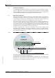
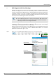
The LCD display can display measured values, parameters, messages and other informa-
tion.
A flashing letter in the upper right corner of the LCD display indicates that a logbook con-
tains unacknowledged logbook entries. Depending on the type of entry this will be:
● "I" for Information
● "W" for Warning
● "E" for Error
After acknowledging all new entries, the letter stops flashing. For details see
pg. 94, 5.4.1.
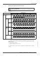
Table 2 Status output
Output signal / LCD / port
Signal behavior
Measurement status Check request status Configuration Mode Data invalid
"Check request"
Status signal
Status
"active / inactive" *
Measurement valid
Status
"active / inactive" *
Compensation of
path failure
"undefined" "undefined"
"Direction of flow"
Status signal
Status
"active / inactive" *
Positive or negative
direction of flow
Status
"active / inactive" *
Positive or negative
direction of flow
"undefined" "undefined"
"Warning"
Status
"active / inactive" *
Status
"active / inactive" *
"undefined" "undefined"
LCD display
Display flashing Display flashing
Serial port RS485
● Measured value, diagnosis information and parameters
● Measuring data logging, diagnosis and configuration through the MEPAFLOW600
CBM software
● Connection with external process control equipment through implemented MODBUS
protocol (data polling)
+V 123456 m³
-V 1234 m³
1234 m³ E
FLOWSIC600
Configuration
+V 123456 m³ E
-V 1234 m³