Vlinx MESR9xx Modbus Gateways Manual Documentation Number MESR9xx-4508m www.bb-elec.com www.bb-europe.
Vlinx MESR9xx Documentation Number: MESR9xx-4508m This product was designed and manufactured in Ottawa, Illinois USA Using domestic and imported parts by International Headquarters B&B Electronics Mfg. Co. Inc. 707 Dayton Road Ottawa, IL 61350 USA Phone (815) 433-5100 -- General Fax (815) 433-5105 Website: www.bb-elec.com European Headquarters B&B Electronics Ltd. Westlink Commercial Park Oranmore, Co. Galway, Ireland Phone +353 91-792444 -- Fax +353 91-792445 Website: www.bb-europe.
Table of Contents Table of Contents 1. Introduction ....................................................................................................................................................... 1 About MESR9xx Modbus Gateways ..........................................................................................................................................1 MESR9xx Modbus Gateway Model Numbering ...............................................................................................
Table of Contents Modbus RTU Message ............................................................................................................................................................25 Modbus Serial Control ..............................................................................................................................................................25 Modbus TCP Message ..................................................................................................................
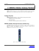
1. Introduction Vlinx MESR9xx Modbus Gateway 1. Introduction Thank you for purchasing a MESR9xx Modbus Gateway product! This product has been manufactured to the highest standards of quality and performance to ensure your complete satisfaction. Figure 1. An MESR921 Modbus Gateway About MESR9xx Modbus Gateways MESR9xx Modbus Gateways connect Modbus networks (RS-232, RS-422 or RS-485) to Ethernet networks, allowing the Modbus network to become a node on the network.
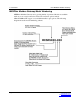
1. Introduction Vlinx MESR9xx Modbus Gateway MESR9xx Modbus Gateway Model Numbering MESR9xx Modbus Gateways are a growing family of products. Models are available with one or two serial connections. Network connection options include 10BaseT/100BaseTX copper or several different fiber optic options. The following diagram shows the model numbering scheme: Page 2 Manual Documentation Number MESR9xx-4508m www.bb-elec.com/ www.bb-europe.
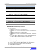
1. Introduction Vlinx MESR9xx Modbus Gateway List of MESR9xx Modbus Gateway Models The following table lists the various MESR9xx Modbus Gateway models available.
1.
1.
2. Hardware Vlinx MESR9xx Modbus Gateway 2. MESR9xx Modbus Gateway Hardware MESR9xx Modbus Gateways are enclosed in DIN rail mountable enclosures and feature LED indicators, power, Ethernet and serial connectors and a recessed Mode switch.
2. Hardware Vlinx MESR9xx Modbus Gateway LED Indicators MESR9xx Modbus Gateways have three types of LED indicators: Ethernet Link LEDs, a Ready LED and Serial Port LEDs. Figure 3. Ready Ethernet Port LEDs on 1 and 2 Ethernet Port Modbus Gateways E1/E2 Ethernet Link LED The Ethernet Link LED (E1 or E2) illuminates (green) if the Ethernet is connected. When the LED is blinking it indicates that there is data traffic on the Ethernet link. E1 is used for all models to connect to the network.
2. Hardware Vlinx MESR9xx Modbus Gateway Mode Switch A recessed momentary reset switch is located on the top of the enclosure. To activate the switch, insert a small plastic tool through the hole in the enclosure and press lightly. Figure 5. Mode Switch The Mode switch can be used to: • • • Initiate a Hardware Reset Enter Console Mode Reload factory defaults Note: Refer to Section 3. Modbus Gateway Setup and Connections for more information on using the Mode switch.
2. Hardware Vlinx MESR9xx Modbus Gateway Fiberoptic Connectors Modbus gateway models using fiber optic network connections use either SC or ST connectors, depending on the specific model. Figure 7.
2. Hardware Vlinx MESR9xx Modbus Gateway Figure 9. Five-Position Pluggable Terminal Block Note: Refer to Appendix D for connection pin-outs. Power Connector The power connector is a 2-position pluggable terminal block. Figure 10. Power Connection Mounting Hardware MESR9xx Modbus Gateway modules can be DIN rail mounted. The DIN mounting clip and spring is included on each module. Page 10 Manual Documentation Number MESR9xx-4508m www.bb-elec.com/ www.bb-europe.
2. Hardware Figure 11. Page 11 Vlinx MESR9xx Modbus Gateway DIN Clips on Modbus Gateway Modules. Large DIN clips are used on MESR92x, small DIN clips on MESR90x. Manual Documentation Number MESR9xx-4508m www.bb-elec.com/ www.bb-europe.
3. Setup and Connections Vlinx MESR9xx Modbus Gateway 3. Modbus Gateway Setup and Connections This section describes how to setup and connect MESR9xx Modbus Gateways. Note: In this section devices to be connected to the Modbus gateway’s serial connection are simply referred to as the “Modbus network”. Connecting the Power Supply Connect a DC power supply to the power terminals on the top of the Modbus gateway. Polarity of the wires is indicated on the label on the side of the Modbus gateway.
3. Setup and Connections Vlinx MESR9xx Modbus Gateway RS-232 connections support eight signal lines plus Signal Ground. Signals are single ended and referenced to Ground. Default communications parameters are 9600, 8, N, 1 and no flow control implemented. RS-422 connections support two signal pairs: RXA(-), RXB(+) and TXA(-), TXA(+), plus GND. The data lines are differential pairs (A & B) in which the B line is positive relative to the A line in the idle (mark) state.
3. Setup and Connections Vlinx MESR9xx Modbus Gateway Figure 13. MESR901 Connections Connecting the MESR9x2T-x The MESR9x2T-x has two serial connections that support RS-232, RS-422 and RS-485 (2- and 4-wire). The unit has two connectors, both of which are 5-position terminal blocks. Make the appropriate connections to the terminal blocks to match the serial connection mode you select when configuring the Modbus gateway. Note: Refer to Appendix D for connector pinout information. Figure 14.
3. Setup and Connections Vlinx MESR9xx Modbus Gateway Note: Refer to Appendix D for connector pinout information. Figure 15. MESR902D-x Connections Connecting MESR9xx Modbus Gateways to a Network Network Connection (10BaseT/100BaseTX) When connecting a Modbus gateway equipped with a 10BaseT/100BaseTX network connection (RJ45 connector) a standard network cable is connected from the Modbus gateway to a network drop.
3. Setup and Connections Vlinx MESR9xx Modbus Gateway Configuring the MESR9xx Modbus Gateway via the Network Connection When configuring via the network, either Vlinx Manager software or the web interface can be used. Configuring with Vlinx Manager MESR9xx Modbus Gateways can be configured over the network Vlinx Manager software running on a PC. To open Vlinx Manager: 1. From the Desktop, click Start Æ Programs Æ B&B Electronics Æ Vlinx Æ Modbus Gateway Manager Æ Configuration Manager.
3. Setup and Connections Vlinx MESR9xx Modbus Gateway To open the web configuration interface: 1. On a PC connected to the network, open a browser. 2. In the browser’s address bar, type the IP address of the Modbus gateway. Note: Your Modbus gateway comes from the factory pre-configured with the IP address 192.168.0.1, but the Vlinx configuration software will automatically configure the correct address through DHCP if this is not available. The web interface Login page appears. Figure 17.
3. Setup and Connections Vlinx MESR9xx Modbus Gateway Figure 18. Console Mode Setup To configure the Modbus gateway it must be put into Console Mode, using the Mode switch. To enter Console Mode, press and hold the Mode switch for between two and ten seconds. The LED indicators respond as follows: 1. The Ready LED blinks three times per second while the button is being pressed. 2. The Modbus gateway is in Console Mode when: • On the MESR901: Port 1 LED is On and the Ready LED is Off.
3. Setup and Connections Vlinx MESR9xx Modbus Gateway Modbus gateway is configured as a TCP server. The socket program running on the PC establishes a communication connection with the Modbus gateway. The data is sent directly to and from the serial port on the server. To set up a Direct IP Mode connection: 1. Connect the Modbus gateway to the network and a Modbus network as described in previous sections. 2.
3. Setup and Connections Vlinx MESR9xx Modbus Gateway Reloading Factory Defaults To reload Factory Defaults, press and hold the Mode switch for more than 10 seconds. The LED indicators respond as follows: 1. The Ready LED blinks three times per second while the button is being pressed. 2. The Modbus gateway is in Factory Default Mode when: • On the MESR901: Port 1 LED and the Ready LED are both On. • On MESR902x models: Port 1 LED and the Port 2 LED are both On.
4. Properties Vlinx MESR9xx Modbus Gateway 4. Description, Modbus Gateway Properties The following MESR9xx Modbus Gateway properties are ordered alphabetically to assist you in finding the information you need. Attached The Attached is selectable between Master and Slaves. If Master is selected, it will run in TCP server mode, if Slaves is selected, it will run in TCP client mode.
4. Properties Vlinx MESR9xx Modbus Gateway Data/Parity/Stop The number of Data bits, type of Parity and number of Stop bits selected define the serial port parameters at which the Modbus gateway will operate. These parameters must be configured to match the parameters set on the Modbus network connected to the Modbus gateway's serial port. Data Bits controls the number of bits of data in each character. Options include 5, 6, 7 or 8 data bits. Parity controls the error checking mode.
4. Properties Vlinx MESR9xx Modbus Gateway If a DHCP server is not found on the network, the Modbus gateway automatically configures to an IP address in the range of 169.254.0.0 through 169.254.255.255 and a subnet mask of 255.255.0.0 MESR9xx Modbus gateways come from the factory with DHCP enabled. Firmware Version The Firmware Version number (Vx.x.x) indicates the Modbus gateway's currently loaded firmware release.
4. Properties Vlinx MESR9xx Modbus Gateway MESR9xxModbus gateways come from the factory with a default static IP address of 192.168.0.1, but will be reconfigured automatically via DHCP as appropriate. If you need to change the static IP address and do not know what address to use, consult your network administrator. Link Status Link Status of the currently selected Modbus gateway is shown on the Login page of Vlinx Manager.
4. Properties Vlinx MESR9xx Modbus Gateway Modbus ASCII The Modbus ASCII message protocol is a human readable version of the Modbus message, and is one of the three Modbus formats supported by the MESR9xx Modbus Gateway. A major advantage of Modbus ASCII is it allows up to a 1 second gap between bytes. It uses a Longitudinal Redundancy Check (LRC) checksum to verify message accuracy. Modbus Message Buffering The MESR9xx has two Modbus serial buffers, one for each serial port.
4. Properties Vlinx MESR9xx Modbus Gateway Character Timeout The character timeout is the maximum time the gateway allows between characters from the slave device, used only in RTU mode. The default is 10ms. CRC/LRC Error Check The CRC/LRC check calculates the CRC/LRC for the message received, and compares this to the CRC/LRC with the message. If not the same the message is rejected.
4. Properties Vlinx MESR9xx Modbus Gateway Password When you first receive the MESR9xx Modbus gateway from the factory the Password is blank so that you can initially access the Modbus gateway without entering a value into this field. To ensure security you should create and save a password the first time you configure the Modbus gateway. After a password has been set up it must be entered each time you login to Vlinx Manager.
4. Properties • Vlinx MESR9xx Modbus Gateway RS-485 4-wire - Similar speed and distance specifications as RS-422 but allows multi-drop and full duplex connections. Typically uses two shielded twisted pairs and screw terminals but DB-9 connectors are also used on MESR9xx Modbus gateways.. Select the appropriate serial interface mode for the type of connection between the Modbus gateway's serial port and the device connected to it. Note: Refer to the Appendix D for connector and pin-out details.
4. Properties • • Vlinx MESR9xx Modbus Gateway For a Class D network (IP addresses 224.0.0.0 through 239.255.255.255) and Class E Networks (IP addresses 240.0.0.0 through 255.255.255.255) the subnet mask is ignored. MESR9xxModbus Gateways come from the factory with a default subnet mask value of: 255.255.255.0 TCP (Transmission Control Protocol) TCP (Transmission Control Protocol) provides reliable connection-oriented network communication with error checking.
5. Upgrading Firmware Vlinx MESR9xx Modbus Gateway 5. Upgrading the Modbus Gateway Firmware Occasionally, updated firmware may become available for your Modbus gateway. The firmware can be upgraded using the Zlinx Manager software. The following procedure describes the firmware updating process: 1. Click the Upgrade button to open the Firmware Upgrade dialog box. Figure 20. Firmware Upgrade Dialog Box The name of the currently selected Modbus gateway appears in the top drop down list.
5. Upgrading Firmware Vlinx MESR9xx Modbus Gateway The current firmware version of the selected Modbus gateway is shown in the text below the Modbus gateway name. Information about the selected firmware file is shown in the third text box. Downloading Firmware Files The Firmware File list (second box) displays all firmware files in the firmware installation folder. Only firmware that is compatible with the selected Modbus gateway is available in this list.
5. Upgrading Firmware Vlinx MESR9xx Modbus Gateway 6. When the upgrade process is complete, click Close. Page 32 Manual Documentation Number MESR9xx-4508m www.bb-elec.com/ www.bb-europe.
6. Diagnostics Vlinx MESR9xx Modbus Gateway 6. Diagnostics Clicking the Diagnostics icon opens the Diagnostics dialog box and enables you to check the operation of connected Modbus gateways on the local computer. The Computer Information box displays information about the type of network connections, the IP addresses, Subnet Masks and Default Gateways in use. Figure 21. Diagnostics Dialog Box Testing a Modbus Gateway Connection To run diagnostics on a Modbus gateway: 1. Click the Diagnostics icon.
6. Diagnostics Vlinx MESR9xx Modbus Gateway 2. In the drop down box select the specific Modbus gateway you want to check. 3. Click the Start button Information about the progress of the pinging process is displayed in the Test Progress box. Figure 22. Page 34 Testing a Modbus Gateway Connection Manual Documentation Number MESR9xx-4508m www.bb-elec.com/ www.bb-europe.
7. Application Examples Vlinx MESR9xx Modbus Gateway 7. Application Examples Modbus gateways can be used to integrate Modbus networks in a wide variety of settings. But as each setting has its own requirements, users may not understand how a gateway helps, or if it’s appropriate for their specific needs. The following scenarios are examples only, and many others are possible. Contact B&B Electronics technical support for information on other applications.
7. Application Examples Vlinx MESR9xx Modbus Gateway From Serial Masters To Ethernet Master, Slave IDs Fixed Legacy Modbus slaves may have fixed IDs. To integrate these into a Modbus TCP network, a multiport MESR model (List here) can assign virtual slave IDs. For information on virtual slave IDs, see (list reference): Figure 25. Scada to Slaves, IDs Fixed Keep Serial Master, Add Ethernet Master(s) In this scenario, the control system is a direct, time-critical serial system.
7. Application Examples Figure 27. Vlinx MESR9xx Modbus Gateway Time Critical Control, Direct and Remotely Monitored Modbus RTU, ASCII, and TCP Integration The range of potential devices and configurations of Modbus serial networks is huge. While simple serial meters are most common, complex manufacturing machines or PLC controllers are also possible. Integration of these devices may involve dealing with different serial environments.
8. Modbus Help Vlinx MESR9xx Modbus Gateway 8. Modbus Help Modbus ASCII/RTU Basics The Modbus protocol emerged in the mid-1970s as an early protocol for linking terminals with Modicon PLCs using a master/slave (sometimes called a master/client) relationship. A simple, open, message-based protocol, it caught on quickly and became a defacto standard in the industry.
8. Modbus Help Vlinx MESR9xx Modbus Gateway Hints and Tips A few simple suggestions that may assist you if your system is experiencing problems include: • • Slowing down the polling rate may be helpful if power cycling doesn’t cure the problem. A common misperception is that every serial network must terminate with a resistor. While this was true of early serial network configurations, it’s typically the wrong answer – call our technical support and verify if you’re an exception, at 815.433.
9. Appendices Vlinx MESR9xx Modbus Gateway 9. Appendices This section includes the following Appendices: • • • • Page 40 Appendix A: Default Gateway Settings Appendix B: Product Specifications Appendix C: Dimensional Diagrams Appendix D: Connector Pinouts Manual Documentation Number MESR9xx-4508m www.bb-elec.com/ www.bb-europe.
9. Appendices Vlinx MESR9xx Modbus Gateway Appendix A: Default Gateway Settings Setting Gateway Name Password DHCP IP Address password field is blank from factory Enabled Net Mask Default 192.168.0.1, DHCP will reconfigure as necessary 255.255.255.0 Gateway 192.168.0.254 MAC Address Fixed - see bottom label Firmware Version (Vx.x.x) Hardware Version (Vx.x.
9. Appendices Vlinx MESR9xx Modbus Gateway Appendix B: Product Specifications This section includes the following specifications: • • • • Page 42 General Specifications Controls, Indicators and Connector Specifications Serial Interface Specifications Network Specifications Manual Documentation Number MESR9xx-4508m www.bb-elec.com/ www.bb-europe.
9.
9.
9.
9. Appendices Vlinx MESR9xx Modbus Gateway Network Specifications Memory Serial Memory Network Memory I/P Port Addresses Network Communications Network Physical Layer Standards Configuration setting in TCP Mode 8888 MESR9xx update 10/100 Mbps Auto-detecting 10BaseT or 100BaseTX IEEE 802.3 auto-detecting & auto MDI/MDX 10BaseT and 100BaseTX TCP, IPv4, ARP, Telnet, HTTP 1.
9. Appendices Vlinx MESR9xx Modbus Gateway Appendix C: Dimensional Diagrams Figure 29. Page 47 Dimensional Diagram of an MESR901 Modbus Gateway (Note: Small Case Used for MESR901 Series Units) Manual Documentation Number MESR9xx-4508m www.bb-elec.com/ www.bb-europe.
9. Appendices Figure 30. Page 48 Vlinx MESR9xx Modbus Gateway Dimensional Diagram of an MESR902T Modbus Gateway (Note: Small Case Used for MESR902 Series Units) Manual Documentation Number MESR9xx-4508m www.bb-elec.com/ www.bb-europe.
9. Appendices Figure 31. Page 49 Vlinx MESR9xx Modbus Gateway Dimensional Diagram of an MESR921 Modbus Gateway, Left and Right Side Views (Note: Medium Case Used for MESR921 and MESR922 Series Units) Manual Documentation Number MESR9xx-4508m www.bb-elec.com/ www.bb-europe.
9. Appendices Figure 32. Page 50 Vlinx MESR9xx Modbus Gateway Dimensional Diagram of an MESR921 Modbus Gateway, Bottom, Top, Back and Front Views (Note: Medium Case Used for MESR921 and MESR922 Series Units) Manual Documentation Number MESR9xx-4508m www.bb-elec.com/ www.bb-europe.
9. Appendices Vlinx MESR9xx Modbus Gateway Appendix D: Connector Pinouts MESR901-x Serial Port Pinouts Page 51 DB-9M Pin RS-232 1 DCD 2 RXD 3 TXD 4 DTR 5 GND 6 DSR 7 RTS 8 CTS 9 RI Manual Documentation Number MESR9xx-4508m www.bb-elec.com/ www.bb-europe.
9. Appendices Page 52 Vlinx MESR9xx Modbus Gateway Terminal RS-422 RS-485 A TXA(-) DATA- B TXB(+) DATA+ C RXA(-) --- D RXB(+) --- E GND GND Manual Documentation Number MESR9xx-4508m www.bb-elec.com/ www.bb-europe.
9. Appendices Vlinx MESR9xx Modbus Gateway MESR902D-x Serial Port Pinouts Page 53 DB-9M Pin RS-232 RS-422 RS-485 1 DCD RXA(-) --- 2 RXD RXB(+) --- 3 TXD TXB(+) DATA+ 4 DTR TXA(-) DATA- 5 GND GND GND 6 DSR --- --- 7 RTS --- --- 8 CTS --- --- 9 RI --- --- Manual Documentation Number MESR9xx-4508m www.bb-elec.com/ www.bb-europe.
9. Appendices Vlinx MESR9xx Modbus Gateway MESR902T-x Serial Port Pinouts Terminal RS-232 RS-422 RS-485 A RTS TXA(-) DATA- B TD TXB(+) DATA+ C CTS RXA(-) --- D RD RXB(+) --- E GND GND GND In the RS-422 mode, TX lines are outputs and RX lines are inputs. Connect the Modbus gateway TXB(+) line to the RXB(+) line of the Modbus network, and the Modbus gateway TXA(-) to the RXA(-) of the Modbus network.
9. Appendices Vlinx MESR9xx Modbus Gateway Standard Ethernet Cable RJ-45 Pin-out Page 55 RJ-45 Pin Signal Wire Color 1 TX+ White-Green 2 TX+ Green 3 RX+ White-Orange 4 Not used Blue 5 Not used White-Blue 6 RX- Orange 7 Not used White-Brown 8 Not used Brown Manual Documentation Number MESR9xx-4508m www.bb-elec.com/ www.bb-europe.
10. Glossary Vlinx MESR9xx Modbus Gateway 10.
10. Glossary Vlinx MESR9xx Modbus Gateway Term Definition A binary digit that is added to ensure that the number of bits with value of Parity Bit one in a given set of bits is always even or odd. It may also be a Mark (1), or a Space (0).