
User Guide


8. Modbus Help Vlinx MESR9xx Modbus Gateway
Page 38 Manual Documentation Number MESR9xx-4508m
www.bb-elec.com/
www.bb-europe.com/
8
8
.
.
M
M
o
o
d
d
b
b
u
u
s
s
H
H
e
e
l
l
p
p
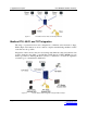
Modbus ASCII/RTU Basics
The Modbus protocol emerged in the mid-1970s as an early protocol for linking terminals
with Modicon PLCs using a master/slave (sometimes called a master/client) relationship.
A simple, open, message-based protocol, it caught on quickly and became a defacto
standard in the industry. It supports asynchronous point-to-point and multidrop
communications and can be used with a variety of serial interfaces (RS-232, RS-422, RS-
485, modems, etc).
The original Modbus specification included two possible transmission modes: ASCII and
RTU. Modbus RTU mode is the most common implementation, using binary coding and
CRC error-checking. Modbus ASCII messages, though somewhat more readable because
they use ASCII characters, is less efficient and uses less effective LRC error checking.
ASCII mode uses ASCII characters to begin and end messages whereas RTU uses time
gaps (3.5 character times) of silence for framing. The two modes are incompatible so a
device configured for ASCII mode cannot communicate with one using RTU.
All Modbus communications are initiated by Modbus masters using a polling
query/response format. The master can send broadcast messages (using a slave address of
0), which all slaves accept, but do not reply to. More commonly the master polls
individual slaves sequentially. In each poll it sends a message containing a device
address, followed by a function code, any data that maybe required, and an error check
field. The addressed slave responds with a similar message structure. Typically it repeats
back its address and the function code, and then sends a field indicating the number of
bytes of data it is sending, followed by the data and the error check field.
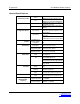
Slave addresses can range from 1 to 247. Function codes include several common ones
typically used in all applications, and additional ones that may be implemented in specific
cases. Common function codes include: Read Coil Status (01), Read Input Status (02),
Read Holding Registers (03) and Read Input Registers (04).
When a master sends a message to a slave it expects to receive a valid response within
certain length of time. If the slave does not receive the message, or if the slave receives
the message but an error is detected, it does not respond. If the slave cannot respond
appropriately for some other reason (e.g. it does not recognize the function code), it will
return a message containing an exception response.