Mini POE Ethernet to RS-232 Converters Models: PES1A, PESV1A Manual Documentation Number: PES1A/PESV1A-4905m pn# 6868-rev001 B&B Electronics Mfg Co Inc – 707 Dayton Rd - PO Box 1040 - Ottawa IL 61350 - Ph 815-433-5100 - Fax 815-433-5104 – www.bb-elec.com B&B Electronics Ltd – Westlink Commercial Park – Oranmore, Galway, Ireland – Ph +353 91-792444 – Fax +353 91-792445 – www.bb-europe.
International Headquarters B&B Electronics Mfg. Co. Inc. 707 Dayton Road Ottawa, IL 61350 USA Phone (815) 433-5100 -- General Fax (815) 433-5105 Website: www.bb-elec.com Sales e-mail: orders@bb-elec.com -- Fax (815) 433-5109 Technical Support e-mail: support@bb.elec.com -- Fax (815) 433-5104 European Headquarters B&B Electronics Ltd. Westlink Commercial Park Oranmore, Co. Galway, Ireland Phone +353 91-792444 -- Fax +353 91-792445 Website: www.bb-europe.com Sales e-mail: sales@bb-europe.
© 2005 B&B Electronics. No part of this publication may be reproduced or transmitted in any form or by any means, electronic or mechanical, including photography, recording, or any information storage and retrieval system without written consent. Information in this manual is subject to change without notice, and does not represent a commitment on the part of B&B Electronics.
CHAPTER 5: USING THE WEB CONFIGURATION AND MANAGEMENT INTERFACE............................................................................................................. 15 Table of Contents LOGGING IN ............................................................................................................. 15 LOGGING OUT ......................................................................................................... 15 USING TUTORIAL AND HELP ...............................................
CHAPTER 8: USING REALPORT....................................................................... 35 Configuring the IP Address................................................................................. 35 Configuring the Serial Port for RealPort............................................................ 35 Adding a Virtual COM Port using RealPort....................................................... 36 Removing a Virtual COM Port using RealPort ..................................................
Introduction Introduction Chapter 1: Introduction PES1A and PESV1A Mini PoE (Power over Ethernet) Ethernet to RS232 Converters provide simple and cost-effective solutions for connecting RS-232 devices to Ethernet networks. PES1A and PESV1A converters make it easy to connect serial printers, copiers, building automation, retail, point of sale, warehousing and banking equipment directly into Ethernet networks.
Introduction Introduction Paired Mode Paired Mode (also called Serial Tunneling or Serial Bridge mode) allows serial devices connected to two PES1A/PESV1A converters to communicate across a network. The two PES1A/PESV1A converters automatically connect to each other. In Paired Mode the heartbeat feature ensures reliable communications by restoring the connection if communications are temporarily lost at either end due to loss of power or Ethernet connection.
Hardware Overview Hardware Overview Indicators, Switches and Connectors Chapter 2: Hardware Overview Link Integrity LED (Yellow) When the yellow LED located on the Ethernet jack is illuminated it indicates that a connection (link integrity) has been established between the converter and a node on the network.
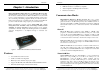
Hardware Overview Hardware Overview Ethernet Port Connector Connecting the Hardware The Ethernet Port connector is a standard RJ-45 receptacle that allows the serial server to be connected to an Ethernet network. It also carries Power over Ethernet (PoE) based on the IEEE 802.3af standard. Typically, the PES1A/PESV1A is connected to a network via a hub, switch or router using standard CAT-5 cable. Power must be supplied to the converter via the CAT-5 cable using Power over Ethernet.
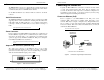
Hardware Overview Hardware Overview Switch or Hub M idspan PoE Power Source* Serial Cable Serial Device PES1A or PESV1A PC PC * Must be w ithin 100 ft of the PES1A/PESV1A Figure 7. Connection using Midspan Power Source Configuration Connections Your PES1A/PESV1A converter typically is configured over the network connection using standard browser software. It also could be connected directly to a PC network adapter. To do so an Ethernet crossover cable is required.
Getting Started Getting Started 6. Configure the PES1A/PESV1A Chapter 3: Getting Started In the Configuration, Serial Ports page select the Port Profile you require for use with your application (E.g. RealPort for virtual COM port, TCP Server, UDP server, Serial Bridge, etc) Configure the serial port settings for the selected Port Profile (E.g. In TCP Sockets select client or server, TCP port numbers, etc.) Also configure baud rate, data bits, etc in Basic Serial Settings. 1.
Configuring the IP Address Configuring the IP Address If you need to change the IP address of the PES1A/PESV1A, you can accomplish this using the discovery software, or you can open the Web Configuration and Management Interface and do it there. (See Configuring Network Settings later in the next chapter.) Chapter 4: Configuring the IP Address Before you can begin the configuration of your PES1A/PESV1A you must know its IP address to access it with a web browser.
Using the Web Configuration and Management Interface Using the Web Configuration and Management Interface Using Tutorial and Help Chapter 5: Using the Web Configuration and Management Interface You can access the PES1A Tutorial by clicking Tutorial on the Configuration and Management homepage. Clicking Help on any page of the Configuration and Management Interface opens topics specific to that page. After logging in, if there is no activity for a period of time your session may time out.
Using the Web Configuration and Management Interface Using the Web Configuration and Management Interface Advanced Network Settings The Advanced Network Settings section allows you to fine-tune the network connection. Typically these setting will not need to be changed. Consult the web-based tutorial and/or your network administrator for more information on Network Services and Advanced Network settings.
Using the Web Configuration and Management Interface Using the Web Configuration and Management Interface TCP Sockets Select TCP Sockets to implement Direct IP Mode using TCP. When using TCP Sockets your converter can be configured as a TCP server or TCP client. TCP Server Settings If your PES1A/PESV1A is configured as a TCP server, other network devices can initiate a TCP connection with the serial device connected to the PES1A/PESV1A serial port. (This is also referred to as reverse telnet.
Using the Web Configuration and Management Interface Using the Web Configuration and Management Interface Figure 15. UDP Server Settings UDP Client Settings If your PES1A/PESV1A is configured as a UDP client you can automatically distribute serial data from you PES1A/PESV1A to many devices at the same time. This is sometimes referred to as Data Distribution or UDP Multicast. Figure 14. TCP Client Settings Consult the Tutorial and online Help for more detail.
Using the Web Configuration and Management Interface Using the Web Configuration and Management Interface Advanced Serial Settings Serial Bridge Click the Advanced Serial Settings menu bar to access settings used to fine tune the serial port. Typically these setting will not need to be changed. Consult the web-based tutorial for more information if necessary. Select Serial Bridge to implement Paired Mode (also called serial tunneling).
Using the Web Configuration and Management Interface Using the Web Configuration and Management Interface GPIO is not supported in the PES1A/PESV1A but it is possible to use the Send alarms based on GPIO pin states feature to generate alarms based on the condition of some RS-232 hardware handshake lines. For assistance in implementing this feature contact B&B Electronics Technical Support at 815 433-511 or support@bb-elec.
Managing the PES1A/PESV1A Managing the PES1A/PESV1A Changing the Root Username and Password Chapter 6: Managing the PES1A/PESV1A You may want to change the Root username and password after you have gained access to the Web Configuration and Management Interface. To change your username and password click Users under the Configuration menu. Follow the prompts to enter a new username and password. Click Apply to complete the procedure.
Managing the PES1A/PESV1A 3. Click the User Access link. The User Access page opens. Select Allow command line access and/or Web Interface Access. Click Apply. (See the online help for more information on these choices.) 4. Click the User Permissions link. The User Permissions page appears containing a list of permissions and dropdown lists. For each item on the list select the level of permission to be granted to the user. (See the online help for more information on these choices.
Using Administrative Features Using Administrative Features System Information Chapter 7: Using Administrative Features The System Information PES1A/PESV1A: page displays information about your General For additional information on each of the following features access the Tutorial and Help files. File Management The File Management page provides facilities to upload and/or manage custom web pages and files such as your applet and HTML files to the PES1A/PESV1A. Uploading an index.htm or index.
Using Administrative Features Using Administrative Features Reboot The Reboot page allows you to reboot the PES1A/PESV1A. If you click on Reboot the process will take approximately one minute to complete. Figure 17. Serial Port Diagnostics Page Network The Network page displays statistics related to IP, TCP, UDP and ICMP protocol activities. Figure 18.
Using RealPort Using RealPort Adding a Virtual COM Port using RealPort Chapter 8: Using RealPort Windows 2000/XP: RealPort is a COM port redirector program that allows you to add and remove virtual COM ports on your PC and update the RealPort software. Virtual COM ports allow you to set up a connection between your PC and the device connected to the serial port on your PES1A/PESV1A via an Ethernet network connection using TCP/IP.
Using RealPort 4. Select the Remove an Existing Device, then click Next. The Select Device to Remove dialog appears listing the IP Address, MAC Address and Model of all devices on the network. To identify your PES1A/PESV1A compare the MAC address listed with the MAC address on the label on your PES1A/PESV1A. 5. Select the device to be removed and click Next. 6. In the Select COM Port dialog that appears, select the COM port number to be assigned to the PES1A/PESV1A. Click Next.
Default Configuration Settings Default Configuration Settings Appendix A: Default Configuration Settings Server Name PES1A, PESV1A Username: root Password: dbps DHCP: Enabled Baud Rate: 9600 Data//Stop: 8/1 Parity: None Flow Control: None TCP/UDP Protocol: TCP Connection Mode: TCP Socket TCP/UDP port: 2001 Manual Documentation Number: PES1A/PESV1A-4905m 39 B&B Electronics Mfg Co Inc – 707 Dayton Rd - PO Box 1040 - Ottawa IL 61350 - Ph 815-433-5100 - Fax 815-433-5104 – www.bb-elec.
Product Specifications Product Specifications Appendix B: Product Specifications Data Bits: 5, 6, 7 or 8 Stop Bits: 1, 2 Flow control: Set-up Options: Model: Manual: CD-ROM disc: Operating Systems supported Dimensions Paper copy of this manual, PDF available RealPort virtual COM port software for Windows 98/ME/2000/XP/NT 4.0 B&B discovery software (finder.
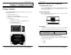
Dimensional Diagrams Dimensional Diagrams Appendix C: Dimensional Diagrams 2.000cm Model PES1A 3.327cm Ethernet 4.204cm RS-232 Power Over Ethernet to RS-232 Converter 9.800cm Figure 19. Dimensional Diagram of the PES1A 13.0 cm 11.7 cm 7.2 cm 10.6 cm Figure 20. Dimensional Diagram of the PESV1A Manual Documentation Number: PES1A/PESV1A-4905m 43 B&B Electronics Mfg Co Inc – 707 Dayton Rd - PO Box 1040 - Ottawa IL 61350 - Ph 815-433-5100 - Fax 815-433-5104 – www.bb-elec.
RS-232 Connections RS-232 Connections Appendix D: RS-232 Connections DB-9M Signal RS-232 DTE 1 Carrier Detect DCD In 2 Receive Data RXD In Pin 3 Transmit Data TXD Out 4 Data Terminal Ready DTR Out 5 Signal Ground GND --- 6 Data Set Ready DSR In 7 Request To Send RTS Out 8 Clear To Send CTS In 9 Not Connected NA NA Figure 21.
Network Connections Network Connections Appendix E: Network Connections PoE PoE Alternative A Alternative B RJ-45 Pin Signal Wire Color 1 TX+ White-Green Negative 2 TX+ Green Negative 3 RX+ White-Orange Positive 4 Not used Blue 5 Not used White-Blue 6 RX- Orange 7 Not used White-Brown Negative 8 Not used Brown Negative Positive Positive Positive Figure 22.
Power over Ethernet Power over Ethernet Device with Power Source Powered End Station 3 Appendix F: Power over Ethernet (PoE) 3 Data Pair Data Pair Power Sourcing Equipment (PSE) Power over Ethernet is a technique (defined by the IEEE802.3af standard) for providing power to Ethernet enabled devices over standard Category 5e cabling. Two techniques (Alternative A and Alternative B) are defined by the standard and supported by the PES1A/PESV1A.
DECLARATION OF CONFORMITY Manufacturer’s Name: B&B Electronics Manufacturing Company Manufacturer’s Address: P.O. Box 1040 707Dayton Road Ottawa, IL 61350 USA Model Numbers: ESR901WB Description: 1 Port 802.11b Wireless Serial Server Type: Light industrial ITE equipment Application of Council Directive: 89/336-EEC Standards: EN 55022 EN 61000-6-1 EN 61000 (-4-1, -4-3, -4-4, -4-5, -4-6, -4-8, -4-11) Robert M.