
Computer Cards Quick Start Guide

Documentation Number: 3PCI-MIport-4004qsg
%%(OHFWURQLFV0IJ&R,QF±'D\WRQ5G32%R[2WWDZD,/3K)D[±ZZZEEHOHFFRP
%%(OHFWURQLFV/WG±:HVWOLQN&RPPHUFLDO3DUN±2UDQPRUH*DOZD\,UHODQG±3K±)D[±ZZZEEHXURSHFRP
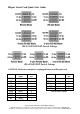
EIA-232-E (RS-232)
Function
PIN #
DB-
25
DB-
9
TO
DTE
TO
DCE
Shield 1
Transmit Data (TD) 2 3 >
Receive Data (RD) 3 2 <
Request To Send
(RTS)
4 7 >
Clear To Send (CTS) 5 8 <
DCE Ready (DSR) 6 6 <
Signal Ground (SG) 7 5
Received Line Signal
Detector (DCD)
8 1 <
DTE Ready (DTR) 20 4 >
Ring Indicator 22 9 -----
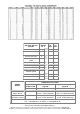
THRESHOLD VOLTAGES
Signal with
Respect to SG
Signal A with Respect to
Signal B
Signal A with Respect to
Signal B
SIGNAL
STATE
RS-232 RS-422 RS-485
"0", Asserted, ON,
Space, Active
+3 to +25 VDC +2 to +6 VDC (Transmitter)
+0.2 to +7 VDC (Receiver)
+1.5 to +6 VDC (Transmitter)
+0.2 to +12 VDC (Receiver)
"1", Disasserted,
OFF, Mark, Inactive
-3 to -25 VDC -2 to -6 VDC (Transmitter)
-0.2 to -7 VDC (Receiver)
-1.5 to -6 VDC (Transmitter)
-0.2 to -7 VDC (Receiver)
NOTE: Some RS-422 and RS-485 equipment use "+" and "-" descriptors.
The "-" corresponds to "A" and the "+" corresponds to "B".