Technical Specifications In This Chapter General Technical Specifications . . . . . . . . . . . . . . . . . . . . . . . . . . . . . . . . . . . . . . . . . . . . . . . . . . . 392 CPU Specifications . . . . . . . . . . . . . . . . . . . . . . . . . . . . . . . . . . . . . . . . . . . . . . . . . . . . . . . . . . . . . . 395 Digital Expansion Modules Specifications . . . . . . . . . . . . . . . . . . . . . . . . . . . . . . . . . . . . . . . . . . . 404 Analog Expansion Modules Specifications . . . .
S7-200 Programmable Controller System Manual General Technical Specifications Standards Compliance The national and international standards listed below were used to determine appropriate performance specifications and testing for the S7-200 family of products. Table A-1 defines the specific adherence to these standards.
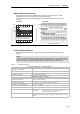
Technical Specifications Appendix A Relay Electrical Service Life The typical performance data supplied by relay vendors is shown in Figure A-1. Actual performance may vary depending upon your specific application. An external protection circuit that is adapted to the load will enhance the service life of the contacts.
S7-200 Programmable Controller System Manual Table A-1 Technical Specifications, continued Electromagnetic Compatibility — Immunity per EN61000--6--21 EN 61000--4--2 Electrostatic discharge 8 kV air discharge to all surfaces and communications port, 4 kV contact discharge to exposed conductive surfaces EN 61000--4--3 Radiated electromagnetic field 10 V/m, 80--1000 MHz, 1.4--2.0 GHz and 2.0--2.
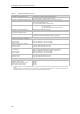
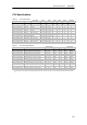
Technical Specifications Appendix A CPU Specifications Table A-2 CPU Order Numbers Order Number Power Supply (Nominal) Digital Inputs Digital Outputs Comm Ports Analog Inputs Analog Outputs Removable Connector 6ES7 211--0AA23--0XB0 CPU 221 24 VDC 6 x 24 VDC 4 x 24 VDC 1 No No No 6ES7 211--0BA23--0XB0 CPU 221 120 to 240 VAC 6 x 24 VDC 4 x Relay 1 No No No 6ES7 212--1AB23--0XB0 CPU 222 24 VDC 8 x 24 VDC 6 x 24 VDC 1 No No No 6ES7 212--1BB23--0XB0 CPU 222 120 to 240 VAC
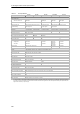
S7-200 Programmable Controller System Manual Table A-4 CPU Specifications CPU 221 CPU 222 CPU 224 CPU 224XP CPU 224XPsi CPU 226 Memory User program size with run mode edit without run mode edit 4096 bytes 4096 bytes 8192 bytes 12288 bytes 12288 bytes 16384 bytes 16384 bytes 24576 bytes User data 2048 bytes 8192 bytes 10240 bytes 10240 bytes Backup (super cap) 50 hours typical (8 hours min. at 40°C) 100 hours typical (70 hours min.
Technical Specifications Table A-5 Appendix A CPU Power Specifications DC AC Input Power Input voltage 20.4 to 28.8 VDC Input current CPU 221 CPU 222 CPU 224 CPU 224XP CPU 224XPsi CPU 226 CPU only at 24 VDC 80 mA 85 mA 110 mA 120 mA 120 mA 150 mA 85 to 264 VAC (47 to 63 Hz) Inrush current 12 A at 28.
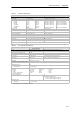
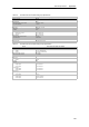
S7-200 Programmable Controller System Manual Table A-7 CPU Digital Output Specifications General 24 VDC Output (CPU 221, CPU 222, CPU 224, CPU 226) 24 VDC Output (CPU 224XP) 24 VDC Output (CPU 224XPsi) Relay Output Type Solid State-MOSFET (Sourcing) Solid State-MOSFET (Sinking) Dry contact Rated voltage 24 VDC 24 VDC 24 VDC 24 VDC or 250 VAC Voltage range 20.4 to 28.8 VDC 5 to 28.8 VDC (Q0.0 to Q0.4) 20.4 to 28.8 VDC (Q0.5 to Q1.1) 5 to 28.
Technical Specifications Table A-8 CPU 224XP and CPU 224XPsi Analog Input Specifications General Analog Input (CPU 224XP, CPU 224XPsi) Number of inputs 2 points Analog input type Single-ended Voltage range ±10 V Data word format, full scale range --32,000 to +32,000 DC Input impedance >100 KΩ Maximum input voltage 30 VDC Resolution 11 bits plus 1 sign bit LSB value 4.88 mV Isolation None Accuracy Worst case 0° to 55° C Typical 25° C Repeatability ±2.5% of full scale ±1.
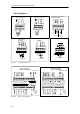
S7-200 Programmable Controller System Manual Wiring Diagrams Used as Sourcing Inputs CPU 224 XP and CPU 224XPsi Analog Input/Output + + 1M .0 .1 .2 1M .0 .3 V LOAD 24 VDC Input Used as Sinking Inputs I LOAD 24 VDC Input .1 .2 .3 M I -+ V M + -- A+ B+ + -- Output Relay Output 24 VDC Output (Sinking) 24 VDC Output (Sourcing) Inputs + N(--) + L(+) 1M 1L+ .0 .1 1M .2 .0 .1 .2 1L CPU 221 DC/DC/DC (6ES7 211--0AA23--0XB0) + 0.1 0.2 0.3 2M 0.4 0.
Technical Specifications CPU 222 DC/DC/DC (6ES7 212--1AB23--0XB0) + + L+ 0.0 0.1 0.2 0.3 0.4 0.5 1M 0.0 0.1 0.2 0.3 2M 0.4 0.5 0.6 0.7 N(--) N(--) L(+) L(+) M L+ DC 1L 0.0 0.1 0.2 M 1M 0.0 0.1 0.2 0.3 2M 0.4 0.5 0.6 0.7 L+ 24 VDC Sensor Power Output 2L 0.3 0.4 0.5 + + + CPU 224 DC/DC/DC (6ES7 214--1AD23--0XB0) M L+ AC + + + L+ DC 1M 0.0 0.1 0.2 0.3 0.4 0.5 0.6 0.7 2M 1.0 1.1 1.2 1.3 1.4 1.
S7-200 Programmable Controller System Manual CPU 224XP DC/DC/DC (6ES7 214--2AD23--0XB0) I LOAD V LOAD V M + I + -- + M -+ 1M 1L+ 0.0 0.1 0.2 0.3 0.4 2M 2L+ 0.5 0.6 0.7 1.0 1.1 M L+ DC 1M 0.0 0.1 0.2 0.3 0.4 0.5 0.6 0.7 2M 1.0 1.1 1.2 1.3 1.4 1.5 M L+ A+ B+ + V M + -- + I 24 VDC Power + M + -+ 24 VDC Sensor Power Output CPU 224XPsi DC/DC/DC (6ES7 214--2AS23--0XB0) CPU 224XPsi Analog I/O 24 VDC Power + CPU 224XP Analog I/O 1M A+ B+ 0.0 0.1 0.2 0.3 0.4 0.5 0.6 0.7 1.0 1.
Technical Specifications Appendix A CPU 226 DC/DC/DC (6ES7 216--2AD23--0XB0) 24 VDC Power + + + 1M 1L+ 0.0 0.1 0.2 0.3 0.4 0.5 0.6 0.7 2M 2L+ 1.0 1.1 1.2 1.3 1.4 1.5 1.6 1.7 1M 0.0 0.1 0.2 0.3 0.4 0.5 0.6 0.7 1.0 1.1 1.2 1.3 1.4 M L+ DC 2M 1.5 1.6 1.7 2.0 2.1 2.2 2.3 2.4 2.5 2.6 2.7 M L+ 24 VDC Power Output + + CPU 226 AC/DC/Relay (6ES7 216--2BD23--0XB0) N(--) N(--) N(--) L(+) L(+) L(+) 1L 0.0 0.1 0.2 0.3 2L 0.4 0.5 0.6 0.7 1.0 3L 120/240 VAC Power 1.1 1.2 1.3 1.4 1.5 1.6 1.
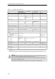
S7-200 Programmable Controller System Manual Digital Expansion Modules Specifications Table A-11 Digital Expansion Modules Order Numbers Order Number Expansion Model Digital Inputs Digital Outputs Removable Connector 6ES7 221--1BF22--0XA0 EM 221 Digital Input 8 x 24 VDC 8 x 24 VDC -- Yes 6ES7 221--1EF22--0XA0 EM 221 Digital Input 8 x 120/230 VAC 8 x 120/230 VAC -- Yes 6ES7 221--1BH22--0XA0 EM 221 Digital Input 16 x 24 VDC 16 x 24 VDC -- Yes 6ES7 222--1BD22--0XA0 EM 222 Digital Output
Technical Specifications Table A-13 Appendix A Digital Expansion Modules Input Specifications General 24 VDC Input 120/230 VAC Input (47 to 63 HZ) Type Sink/Source (IEC Type 1 sink) IEC Type I Rated voltage 24 VDC at 4 mA 120 VAC at 6 mA or 230 VAC at 9 mA nominal Maximum continuous permissible voltage 30 VDC 264 VAC Surge voltage (max.) 35 VDC for 0.5 s -- Logic 1 (min.) 15 VDC at 2.5 mA 79 VAC at 2.5 mA Logic 0 (max.) 5 VDC at 1 mA 20 VAC or 1 mA AC Input delay (max.) 4.
S7-200 Programmable Controller System Manual Table A-14 Digital Expansion Modules Output Specifications 24 VDC Output General 0.75 A Relay Output 5A 2A 120/230 VAC Output 10 A Type Solid state-MOSFET (Sourcing) Dry contact Rated voltage 24 VDC 24 VDC or 250 VAC Voltage range 20.4 to 28.8 VDC 5 to 30 VDC or 5 to 250 VAC 24 VDC coil power voltage range -- 20.4 to 28.8 VDC Surge current (max.) 8 A for 100 ms Logic 1 (min.) 20 VDC -- L1 (--0.9 V rms) Logic 0 (max.) 0.
Technical Specifications 120/230 AC Output Relay Output 24 VDC Output Appendix A N L1 N(--) + L(+) 1M 1L+ .0 .1 0L .2 1L Figure A-8 .0 .1 0L .0 .2 S7-200 Digital Expansion Modules Outputs Wiring Diagrams EM 223 24 VDC Digital Combination 4 Inputs/4 Relay Outputs (6ES7 223--1HF22--0XA0) + .2 .3 1M .0 .1 .2 .3 + Figure A-9 N(--) N(--) L(+) L(+) L(+) .0 .1 .2 .3 1M .0 .1 .2 .3 1L M 24 VDC Coil Power + .1 N(--) L+ + 1M 1L+ .
S7-200 Programmable Controller System Manual EM 221 Digital Input 8 x 24 VDC (6ES7 221--1BF22--0XA0) EM 221 Digital Input 16 x 24 VDC (6ES7 221--1BH22--0XA0) + .2 .3 2M .4 .5 .6 .7 1M .0 .1 .2 .3 2M .4 .5 .6 .7 3M .0 .1 .2 .3 4M .4 .5 .6 .7 + + .1 + 1M .0 + + EM 221 Digital Input 8 x AC 120//230 V (6ES7 221--1EF22--0XA0) EM 222 Digital Output 8 x AC 120/230 V (6ES7 222--1EF22--0AX0) N L1 0N 0N .0 4N .4 1N 1N .1 2N 2N .2 3N 3N .3 5N 5N .5 .6 7N 7N .
Technical Specifications EM 223 24 VDC Digital Combination 8 Inputs/8 Outputs (6ES7 223--1BH22--0XA0) EM 223 24 VDC Digital Combination 8 Inputs/8 Relay Outputs (6ES7 223--1PH22--0XA0) N(--) N(--) + .2 .3 2M 2L+ .4 .5 .6 .7 1M .0 .1 .2 .3 .5 .6 .7 2M .4 1L 24VDC Coil Power .0 .1 .2 .3 2L .4 .5 .6 .7 M L+ 1M .0 .1 .2 .3 2M .4 .5 .6 .7 + .1 L(+) + + 1M 1L+ .
S7-200 Programmable Controller System Manual EM 223 24 VDC Digital Combination 32 Inputs/32 Outputs (6ES7 223--1BM22--0XA0) + + 1M 1L+ 0.0 0.1 0.2 0.3 0.4 0.5 0.6 0.7 1.0 1.1 1.2 1.3 1.4 1.5 1.6 1M 0.0 0.1 0.2 0.3 0.4 0.5 0.6 0.7 1.0 1.1 1.2 1.3 1.7 2M 2L+ 2.0 1.4 1.5 1.6 1.7 2.1 2.2 2.3 2.4 2.5 2.6 2.7 3.0 3.1 3.2 3.3 3.4 3.5 2M 2.0 2.1 2.2 2.3 2.4 2.5 2.6 2.7 3.0 3.1 3.2 3.3 3.4 3.5 3.6 3.7 3.6 3.
Technical Specifications Appendix A Analog Expansion Modules Specifications Table A-15 Analog Expansion Modules Order Numbers Order Number Expansion Model EM Inputs EM Outputs Removable Connector 6ES7 231--0HC22--0XA0 EM 231 Analog Input, 4 Inputs 4 -- No 6ES7 231--0HF22--0XA0 EM 231 Analog Input, 8 Inputs 8 -- No 6ES7 232--0HB22--0XA0 EM 232 Analog Output, 2 Outputs -- 2 No 6ES7 232--0HD22--0XA0 EM 232 Analog Output, 4 Outputs -- 4 No 6ES7 235--0KD22--0XA0 EM 235 Analog Combin
S7-200 Programmable Controller System Manual Table A-18 Analog Expansion Modules Output Specifications General Isolation (field to logic) Signal range Voltage output Current output Resolution, full-scale Voltage Current Data word format Voltage Current Accuracy Worst case, 0° to 55° C Voltage output Current output Typical, 25° C Voltage output Current output Setting time Voltage output Current output Maximum drive Voltage output Current output 24 VDC supply voltage range 412 6ES7 232-- 0HB22-- 0XA0 6ES
Technical Specifications EM 231 Analog Input, 4 Inputs (6ES7 231--0HC22--0XA0) Current PS PS L+ EM 231 Analog Input, 8 Inputs (6ES7 231--0HF22--0XA0) M + Voltage Unused +-- 0--20mA + Normal voltage input 4--20mA -- Appendix A Short unused inputs -M RA A+ A-- RB B+ B-- RC C+ C-- RD D+ D-- 250 Ohms (built-in) M L+ Gain Configuration + + 24 VDC Power Supply 24 VDC Power M0 V0 M I0 EM 232 Analog Output, 4 Outputs (6ES7 232--0HD22--0XA0) I LOAD V LOAD I LOAD V LOAD EM 232 Analog Outp
S7-200 Programmable Controller System Manual EM 235 Analog Combination 4 Inputs/1 Output (6ES7 235--0KD22--0XA0) Voltage PS 0--20mA Unused +-- Current PS + L+ M 4--20mA -- -M RA A+ A-- RB B+ B-- RC C+ C-- RD D+ D-- 250 Ohms (built-in) M0 + V0 I0 Gain Offset Configuration I LOAD L+ V LOAD M 24 VDC Power Figure A-14 Wiring Diagrams for Analog Expansion Modules Analog LED Indicators The LED indicators for the analog modules are shown in Table A-19.
Technical Specifications Appendix A Input Calibration The calibration adjustments affect the instrumentation amplifier stage that follows the analog multiplexer (see the Input Block Diagram for the EM 231 in Figure A-17 and EM 235 in Figure A-19). Therefore, calibration affects all user input channels.
S7-200 Programmable Controller System Manual Configuration for EM 231 Table A-20 and Table A-21show how to configure the the EM 231 modules using the configuration DIP switches. All inputs are set to the same analog input range. In these tables, ON is closed, and OFF is open. The switch settings are read only when the power is turned on. For the EM 231 Analog Input, 4 Inputs module, switches 1, 2, and 3 select the analog input range (Table A-20).
Technical Specifications Appendix A Configuration for EM 235 Table A-22 shows how to configure the EM 235 module using the configuration DIP switches. Switches 1 through 6 select the analog input range and resolution. All inputs are set to the same analog input range and format. Table A-22 shows how to select for unipolar/bipolar (switch 6), gain (switches 4 and 5), and attenuation (switches 1, 2, and 3). In these tables, ON is closed, and OFF is open.
S7-200 Programmable Controller System Manual Input Data Word Format for EM 231 and EM 235 Figure A-16 shows where the 12-bit data value is placed within the analog input word of the CPU. MSB 15 14 AIW XX 3 Data value 12 Bits 0 LSB 0 2 0 0 0 Unipolar data MSB 15 4 AIW XX Data value 12 Bits LSB 0 3 0 0 0 0 Bipolar data Figure A-16 Input Data Word Format for EM 231 and EM 235 Tip The 12 bits of the analog-to-digital converter (ADC) readings are left-justified in the data word format.
Technical Specifications Appendix A EM 231 Analog Input, 8 Inputs GAIN ADJUST Instrumentation AMP BUFFER A/D Converter MUX 8 to 1 Input filter Figure A-18 Input Block Diagram for the EM231 Analog Input, 8 Inputs EM 235 A+ R RA C C C Rloop A-- GAIN ADJUST A=1 R + B+ R RB C Rloop C B-- Instrumentation AMP C R BUFFER A/D Converter -A=2 11 C+ R RC C C Rloop C-- 0 DATA REF_VOLT C + Buffer -- A=3 R Offset Adjust D+ R RD C C Rloop C D-R Input filter Figure A-19
S7-200 Programmable Controller System Manual MSB 15 14 AQW XX 0 AQW XX Figure A-20 Data value 11 Bits Current output data format MSB 15 4 3 0 4 Data value 12 Bits Voltage output data format 3 0 0 LSB 0 0 0 0 LSB 0 0 0 Output Data Word Format for EM 232 and EM 235 Tip The 12 bits of the digital-to-analog converter (DAC) readings are left-justified in the output data word format. The MSB is the sign bit: zero indicates a positive data word value.
Technical Specifications Appendix A Installation Guidelines Use the following guidelines to ensure accuracy and repeatability: - Ensure that the 24-VDC Sensor Supply is free of noise and is stable. - Use the shortest possible sensor wires. - Use shielded twisted pair wiring for sensor wires. - Terminate the shield at the Sensor location only. - Short the inputs for any unused channels, as shown in Figure A-21. - Avoid bending the wires into sharp angles. - Use wireways for wire routing.
S7-200 Programmable Controller System Manual Definitions of the Analog Specifications - Accuracy: deviation from the expected value on a given point - Resolution: the effect of an LSB change reflected on the output. Table A-23 EM 231 and EM 235 Specifications Full Scale Input Range Repeatability1 % of Full Scale Mean (average) Accuracy1,2,3,4 Counts % of Full Scale Counts EM 231 Specifications 0 to 5 V 0 to 20 mA 0 to 10 V ± 24 ± 0.1% ± 0.075% ± 2.5 V ± 32 ± 48 ±5V ±0 0.
Technical Specifications Appendix A Thermocouple and RTD Expansion Modules Specifications Table A-24 Thermocouple and RTD Modules Order Numbers Order Number Expansion Model Removable Connector EM Outputs 6ES7 231--7PD22--0XA0 EM 231 Analog Input Thermocouple, 4 Inputs 4 Thermocouple -- No 6ES7 231--7PB22--0XA0 EM 231 Analog Input RTD, 2 Inputs 2 RTD -- No Table A-25 Thermocouple and RTD Modules General Specifications Order Number Dimensions (mm) (W x H x D) Module Name and Description
S7-200 Programmable Controller System Manual EM 231 Analog Input Thermocouple, 4 Inputs (6ES7 231--7PD22--0XA0) + -- + -- + -- + -- A+ A -- B+ B-- C+ C-- D+ D-EM 231 AI 4 M EM 231 Analog Input RTD, 2 Inputs (6ES7 231--7PB22--0XA0) Configuration L+ A+ A -- a+ a-- B+ B-- b+ b-EM 231 AI 2 x RTD M L+ Configuration + + -- -- 24 VDC power 24 VDC power Figure A-23 Connector Terminal Identification for EM 231 Thermocouple and EM 231 RTD Modules Compatibility The RTD and Thermocouple modules ar
Technical Specifications Appendix A EM 231 Thermocouple Module The EM 231 Thermocouple module provides a convenient, isolated interface for the S7-200 family to seven thermocouple types: J, K, E, N, S, T, and R. It allows the S7-200 to connect to low level analog signals, ±80mV range. All thermocouples attached to the module must be of the same type. Thermocouple Basics Thermocouples are formed whenever two dissimilar metals are electrically bonded to each other.
S7-200 Programmable Controller System Manual Table A-27 Configuring the Thermocouple Module DIP Switches Switches 1,2,3 Thermocouple Type SW1, 2, 3 1 2 3 4* 5 6 7 8 Configuration ↑1 -- On ↓ -- Off ↓0 * Set S t DIP switch it h 4 to the 0 (down) position. Switch 5 1 2 3 4 5 6 7 8 Co gu at o Configuration ↑1 -- On O ↓0 -- Off Switch 6 Configuration ↑1 -- On ↓0 -- Off Switch 8 010 E 011 R 100 S 101 N 110 +/--80mV 111 Setting Upscale (+3276.7 degrees) 0 Downscale (--3276.
Technical Specifications Appendix A Tip H The open wire current source could interfere with signals from some low level sources such as thermocouple simulators. H Input voltages exceeding approximately ±200mV will trigger open wire detection even when the open wire current source is disabled. Tip H Module error could exceed specifications while the ambient temperature is changing. H Exceeding the module ambient temperature range specification could cause the module cold junction to be in error.
S7-200 Programmable Controller System Manual Table A-29 Temperature Ranges (°C) and Accuracy for Thermocouple Types Data Word (1 digit = 0.1_C) Dec Type J Hex Type R R, S Type N >1000.0_C >1768.0_C >1300.0_C ¦80mV 7FFF >94.071mV OF ↑ ↑ ↑ 32511 7EFF 94.071mV : : 27649 6C01 27648 6C00 : : 17680 4510 : : 13720 3598 : : 13000 32C8 : : 12000 2EE0 : : 10000 2710 : : 4000 0FA0 : : 1 0001 0.1_C 0.1_C 0.1_C 0.1_C 0.1_C 0.1_C 0.0029mV 0 0000 0.0_C 0.
Technical Specifications Table A-30 Appendix A Temperature Ranges (°F) for Thermocouple Types Data Word (1 digit = 0.1°F) Dec Hex 32767 7FFF ↑ ↑ 32511 7EFF 32140 7D90 27649 6C01 27648 6C00 Type J >2192.0 _F Type K >2502.0 _F Type T >752.0 _F Type E >1832.0_F Type R, S >3214.0_F Type N >2372.0_F ↑ ¦80 mV >94.071mV OF ↑ ↑ 94.071mV OR 3214.0_F 80.0029mV 80mV ↑ NR 2764.8_F : : 25020 61B8 2502.
S7-200 Programmable Controller System Manual EM 231 RTD Module The EM 231 RTD module provides a convenient interface for the S7-200 family to several different RTDs. It also allows the S7-200 to measure three different resistance ranges. Both RTDs attached to the module must be of the same type. Configuring the EM 231 RTD Module DIP switches enable you to select RTD type, wiring configuration, temperature scale, and burnout direction.
Technical Specifications Table A-32 Setting RTD DIP Switches Switch 6 Open Wire Detect/ Out of Range SW6 1 2 3 4 5 6 7 8 Configuration ↑1 -- On ↓0 -- Off 1 2 3 4 5 6 7 8 Configuration ↑1 -- On ↓0 -- Off Indicates positive on open wire or out of range Downscale (--3276.
S7-200 Programmable Controller System Manual EM 231 RTD Status Indicators The RTD module provides the PLC with data words that indicate temperatures or error conditions. Status bits indicate range error and user supply/module failure. LEDs indicate the status of the module. Your program should have logic to detect error conditions and respond appropriately for the application. Table A-33 shows the status indicators provided by the EM 231 RTD module.
Technical Specifications Appendix A EM 231 RTD Module Ranges EM 231 RTD temperature ranges and accuracy for each type of RTD module are shown in Tables A-34 and A-35. Table A-34 Temperature Ranges (°C) and Accuracy for RTD Types System Word (1 digit = 0.1 _C) Decimal Pt10000 Hex Pt100, Pt200, Pt500, Pt1000 Pt500 Ni100, Ni120, Ni10001 Cu10 0 - 150Ω 0 - 300Ω 0 - 600Ω 32767 7FFF 32766 7FFE ↑ ↑ ↑ 32511 7EFF 176.383Ω 352.767Ω 705.534Ω 29649 6C01 150.005Ω 300.011Ω 600.
S7-200 Programmable Controller System Manual Table A-35 Temperature Ranges (°F) for RTD Types System Word (1 digit = 0.1 _F) Decimal PT1000 Hexadecimal 32767 7FFF 32766 7PHAGE PT100, Pt200, Pt500, Pt1000 Ni100, Ni120, Ni10001 Cu 10 ↑ Overrange 18320 4790 15620 3D04 11120 2B70 ↑ ↑ 1832.0_F 1832.0 _F 1562.0_F 1112.0_F ↑ 5936 1730 ↑ 5630 15FE 563.0_F 593.6_F 5000 1388 4820 12D4 1 0001 0.1_F 0.1_F 0.1_F 0.1_F 0 0000 0.0_F 0.0_F 0.0_F 0.0_F --1 FFFF --0.1_F --0.
Technical Specifications Appendix A EM 277 PROFIBUS--DP Module Specifications Table A-36 EM 277 PROFIBUS--DP Module Order Number Order Number Expansion Model 6ES7 277--0AA22--0XA0 Table A-37 EM Inputs EM 277 PROFIBUS--DP -- EM Outputs -- Removable Connector No EM 277 PROFIBUS--DP Module General Specifications Module Name and Description Order Number 6ES7 277--0AA22--0XA0 EM 277 PROFIBUS--DP Dimensions (mm) (W x H x D) 71 x 80 x 62 Weight 175 g Dissipation 2.
S7-200 Programmable Controller System Manual S7-200 CPUs that Support Intelligent Modules The EM 277 PROFIBUS--DP slave module is an intelligent expansion module designed to work with the S7-200 CPUs shown in Table A-39. Table A-39 EM 277 PROFIBUS--DP Module Compatibility with S7-200 CPUs CPU Description CPU 222 Rel. 1.10 or greater CPU 222 DC/DC/DC and CPU 222 AC/DC/Relay CPU 224 Rel. 1.10 or greater CPU 224 DC/DC/DC and CPU 224 AC/DC/Relay CPU 224XP Rel. 2.
Technical Specifications Appendix A Distributed Peripheral (DP) Standard Communications PROFIBUS--DP (or DP Standard) is a remote I/O communications protocol defined by the European Standard EN 50170. Devices that adhere to this standard are compatible even though they are manufactured by different companies. DP stands for distributed peripherals, that is, remote I/O. PROFIBUS stands for Process Field Bus.
S7-200 Programmable Controller System Manual The DP port of the EM 277 PROFIBUS--DP module can be attached to a DP master on the network and still communicate as an MPI slave with other master devices such as SIMATIC programming devices or S7-300/S7-400 CPUs on the same network. Figure A-27 shows a PROFIBUS network with a CPU 224 and an EM 277 PROFIBUS--DP module. - - - The CPU 315--2 is the DP master and has been configured by a SIMATIC programming device with STEP 7 programming software.
Technical Specifications Appendix A Tip If you are working with a data unit (consistent data) of three bytes or data units greater than four bytes, you must use SFC14 to read the inputs of the DP slave and SFC15 to address the outputs of the DP slave. For more information, see the System Software for S7-300 and S7-400 System and Standard Functions Reference Manual. Table A-40 lists the configurations that are supported by the EM 277 PROFIBUS--DP module.
S7-200 Programmable Controller System Manual Data Consistency PROFIBUS supports three types of data consistency: - - Byte consistency ensures that bytes are transferred as whole units. Word consistency ensures that word transfers cannot be interrupted by other processes in the CPU (the two bytes composing the word are always moved together and cannot be split). Use Word consistency if the data values being transferred are integers.
Technical Specifications Appendix A Status Information There are 50 bytes of special memory (SM) allocated to each intelligent module based on its physical position. The module updates the SM locations corresponding to the modules’ relative position to the CPU (with respect to other modules). If it is the first module, it updates SMB200 through SMB249. If it is the second module, it updates SMB250 through SMB299, and so on. See Table A-41.
S7-200 Programmable Controller System Manual LED Status Indicators for the EM 277 PROFIBUS-- DP The EM 277 PROFIBUS--DP module has four status LEDs on the front panel to indicate the operational state of the DP port: - After the S7-200 CPU is turned on, the DX MODE LED remains off as long as DP communications are not attempted.
Technical Specifications PROFIBUS--DP Master S7-300 XPUTS/XGETS Functions PROFIBUS--DP STEP 7--Micro/WIN1 MPI MPI Appendix A TD 2001,2 MPI PROFIBUS--DP/MPI PROFIBUS--DP MPI EM 277 PROFIBUS--DP Module 1) 2) Communications are possible only to the S7-200 CPUs and the EM 277. TD 200 must be Rel 2.0 or greater. S7-22x CPU Figure A-30 PROFIBUS--DP/MPI Network Device Database File: GSD Different PROFIBUS devices have different performance characteristics.
S7-200 Programmable Controller System Manual ;================================================ ; GSD File for the EM 277 PROFIBUS-DP with a DPC31 ; MLFB : 6ES7 277-0AA2.-0XA0 ; DATE : 26-March-2001 ;================================================ #Profibus_DP ;General parameters GSD_Revision = 1 Vendor_Name = ”Siemens” Model_Name = ”EM 277 PROFIBUS-DP” Revision = ”V1.02” Ident_Number = 0x089D Protocol_Ident = 0 Station_Type = 0 FMS_supp = 0 Hardware_Release = ”1.00” Software_Release = ”1.02” 9.
Technical Specifications Appendix A Sample Program for DP Communications to a CPU A sample program in Statement List for the PROFIBUS--DP module in slot 0 for a CPU that uses the DP port information in SM memory is shown below. The program determines the location of the DP buffers from SMW226 and the sizes of the buffers from SMB228 and SMB229. This information is used to copy the data in the DP output buffer to the process-image output register of the CPU.
S7-200 Programmable Controller System Manual Example of DP Communications to a CPU Network 1 LDB= MOVD ITD +D Network 2 LDB= MOVD BTI ITD +D Network 3 //Calculate the Output data pointer. //If in data exchange mode: //1. Output buffer is an offset from VB0 //2. Convert Vmem offset to double integer //3. Add to VB0 address to get output data // pointer. SMB224, 2 &VB0, VD1000 SMW226, AC0 AC0, VD1000 //Calculate the Input data pointer. //If in data exchange mode: //1. Copy the output data pointer //2.
Technical Specifications Appendix A EM 241 Modem Module Specifications Table A-44 EM 241 Modem Module Order Number Order Number Expansion Model 6ES7 241--1AA22--0XA0 EM Inputs EM 241 Modem Module EM Outputs 81 -- Removable Connector No 1 Eight Q outputs are used as logical controls of the modem function and do not directly control any external signals.
S7-200 Programmable Controller System Manual S7-200 CPUs that Support Intelligent Modules The EM 241 Modem module is an intelligent expansion module designed to work with the S7-200 CPUs shown in Table A-47. Table A-47 EM 241 Modem Module Compatibility with S7-200 CPUs CPU Description CPU 222 Rel. 1.10 or greater CPU 222 DC/DC/DC and CPU 222 AC/DC/Relay CPU 224 Rel. 1.10 or greater CPU 224 DC/DC/DC and CPU 224 AC/DC/Relay CPU 224XP Rel 2.
Technical Specifications Appendix A EM 253 Position Module Specifications Table A-49 EM 253 Position Module Order Number Order Number Expansion Model 6ES7 253--1AA22--0XA0 1 Eight EM Inputs EM 253 Position Module EM Outputs 81 -- Removable Connector Yes Q outputs are used as logical controls of the motion function and do not directly control any external signals.
S7-200 Programmable Controller System Manual Table A-51 EM 253 Position Module Specifications, continued General 6ES7 253-- 1AA22-- 0XA0 Output Features Number of integrated outputs Output type P0+, P0--, P1+, P1-P0, P1, DIS, CLR Output voltage P0, P1, RS--422 drivers, differential output voltage Open circuit Into optocoupler diode with 200Ω series resistance 100Ω load 54Ω load P0, P1, DIS, CLR open drain recommended voltage, open circuit permissible voltage, open circuit Sink current On state resistanc
Technical Specifications Appendix A S7-200 CPUs that Support Intelligent Modules The EM 253 Position module is an intelligent expansion module designed to work with the S7-200 CPUs shown in Table A-52. Table A-52 EM 253 Position Module Compatibility with S7-200 CPUs CPU Description CPU 222 Rel. 1.10 or greater CPU 222 DC/DC/DC and CPU 222 AC/DC/Relay CPU 224 Rel. 1.10 or greater CPU 224 DC/DC/DC and CPU 224 AC/DC/Relay CPU 224XP Rel 2.
S7-200 Programmable Controller System Manual Wiring Diagrams In the following schematic figures, the terminals are not in order. See Figure A-34 for terminal arrangement. +5VDC L+ T1 P/S 3.3K P0 M STOP 5.6K 3.3K 1K P1 1M RPS 5.6K 3.3K DIS 1K 2M ZP 3.3K CLR 3M LMT+ P0+ 5.6K P0-- 1K LMT-- P1+ 5.6K P1-M 1K M 4M Figure A-35 Internal Schematic for the Inputs and Outputs of the EM 253 Position Module EM253 Motion Module +24V FM Step Drive +24V +5VDC L+ T1 P/S 24V_RTN GATE_N 3.
Technical Specifications EM253 Motion Module +24V Appendix A Industrial Devices Corp. (Next Step) +5VDC L+ T1 P/S 24V_RTN 3.3K P0 M STOP 3.3K P1 1M + RPS 3.3K Terminals are not in order. See Figure A-34 for terminal arrangement. SD DIS 2M ZP 3.3K CLR 3M P0+ + LMT+ STP P0-P1+ LMT-- + DIR P1-M M 4M Figure A-37 Connecting an EM 253 Position Module to a Industrial Devices Corp. (Next Step) EM253 Motion Module +24V Oriental Motor UPK Standard +5VDC L+ + T1 P/S 24V_RTN 3.
S7-200 Programmable Controller System Manual EM253 Motion Module +24V Parker/Compumotor OEM 750 +5VDC L+ T1 P/S 24V_RTN 3.3K P0 M STOP 3.3K DIR P1 1M RPS 3.3K Terminals are not in order. See Figure A-34 for terminal arrangement. DIS 2M ZP 3.
Technical Specifications Appendix A (CP 243--1) Ethernet Module Specifications Table A-54 (CP 243--1) Ethernet Module Order Number Order Number Expansion Module 6GK7 243--1EX00--OXE0 EM Inputs (CP 243--1) Ethernet Module EM Outputs 81 -- Removable Connector No 1 Eight Q outputs are used as logical controls of Ethernet function and do not directly control any external signals.
S7-200 Programmable Controller System Manual S7-200 CPUs that Support Intelligent Modules The (CP 243--1) Ethernet module is an intelligent expansion module designed to work with the S7-200 CPUs shown in Table A-47. Table A-57 (CP 243--1) Ethernet Module Compatibility with S7-200 CPUs CPU Description CPU 222 Rel. 1.10 or greater CPU 222 DC/DC/DC and CPU 222 AC/DC/Relay CPU 224 Rel. 1.10 or greater CPU 224 DC/DC/DC and CPU 224 AC/DC/Relay CPU 224XP Rel. 2.
Technical Specifications Appendix A (CP 243--1 IT) Internet Module Specifications Table A-58 (CP 243--1 IT) Internet Module Order Number Order Number Expansion Module 6GK7 243--1GX00--OXE0 EM Inputs (CP 243--1 IT) Internet Module EM Outputs Removable Connector 81 -- No 1 Eight Q outputs are used as logical controls of the IT function and do not directly control any external signals.
S7-200 Programmable Controller System Manual The (CP 243--1 IT) Internet module is a communications processor used for connecting the S7-200 system to Industrial Ethernet (IE). The S7-200 can be remotely configured, programmed and diagnosed via Ethernet using STEP 7 Micro/WIN. The S7-200 can communicate with another S7--200, S7-300, or S7-400 controller via Ethernet. It can also communicate with an OPC server.
Technical Specifications Appendix A Configuration Internet You can use the STEP 7--Micro/WIN Internet Wizard to configure the (CP 243--1 IT) Internet module to connect an S7-200 PLC to an Ethernet/Internet network. The (CP 243--1 IT) Internet module has additional web server functionality that can be configured with the Internet Wizard. To start the Internet Wizard, select the Tools > Internet Wizard menu command. Connections The (CP 243--1 IT) Internet module has the following connections.
S7-200 Programmable Controller System Manual (CP 243--2) AS--Interface Module Specifications Table A-62 (CP 243--2) AS-Interface Module Order Number Order Number Expansion Model 6GK7 243--2AX01--0XA0 Table A-63 EM Outputs 8 Digital and 8 Analog 8 Digital and8 Analog Removable Connector Yes (CP 243--2) AS-Interface Module General Specifications Module Name and Description Order Number 6GK7 243--2AX01--0XA0 Table A-64 EM Inputs (CP 243--2) AS--Interface Module (CP 243--2) AS--Interface Module
Technical Specifications Appendix A Operation In the process image of the S7-200, the AS--Interface Module occupies a digital input byte (status byte), a digital output byte (control byte), 8 analog input and 8 analog output words. The AS--Interface Module uses two logical module positions. You can use the status and the control byte to set the mode of the AS--Interface Module using a user program.
S7-200 Programmable Controller System Manual Optional Cartridges Cartridge Description Order Number Memory cartridge Memory cartridge, 64K (user program, recipe, and data logging) 6ES7 291--8GF23--0XA0 Memory cartridge Memory cartridge, 256K (user program, recipe, and data logging) 6ES7 291--8GH23--0XA0 Real-Time Clock with battery Clock cartridge accuracy: 2 minutes/month at 25°C, 7 minutes/month at 0°C to 55°C 6ES7 297--1AA23--0XA0 Battery cartridge Battery cartridge (data retention time): 2
Technical Specifications Appendix A I/O Expansion Cable General Features (6ES7 290-- 6AA20-- 0XA0) Cable length 0.8 m Weight 25 g Connector type 10 pin ribbon Female Connector Male Connector Figure A-43 Typical Installation of the I/O Expansion Cable Tip Only one expansion cable is allowed in a CPU/expansion module chain.
S7-200 Programmable Controller System Manual RS-232/PPI Multi-Master Cable and USB/PPI Multi-Master Cable Table A-66 RS-232/PPI Multi-Master Cable and USB/PPI Multi-Master Cable Specifications Description Order Number S7-200 RS-232/PPI Multi-Master Cable 6ES7 901-- 3CB30-- 0XA0 S7-200 USB/PPI Multi-Master Cable 6ES7-- 901-- 3DB30-- 0XA0 General Characteristics Supply voltage 14.4 to 28.8 VDC 14.4 to 28.8 VDC Supply current at 24 V nominal supply 60 mA RMS max. 50 mA RMS max.
Technical Specifications Appendix A S7-200 RS-232/PPI Multi-Master Cable Table A-67 S7-200 RS-232/PPI Multi--Master Cable -- Pin-outs for RS-485 to RS-232 Local Mode Connector RS-485 Connector Pin-out Pin Number 1 Signal Description RS-232 Local Connector Pin-out Pin Number Signal Description 1 No connect 1 Data Carrier Detect (DCD) (not used) 2 24 V Return (RS-485 logic ground) 2 Receive Data (RD) (output from PC/PPI cable) 3 Signal B (RxD/TxD+) 3 Transmit Data (TD) (input to PC/PPI cab
S7-200 Programmable Controller System Manual Use the S7-200 RS-232/PPI Multi-Master Cable with STEP 7--Micro/WIN 3.2 Service Pack 4 (or later) For connection directly to your personal computer: - Set the PPI mode (Switch 5=1) - Set Local (Switch 6=0) - Set 11--bit mode (Switch 7=0) For connection to a modem: - Set the PPI mode (Switch 5=1) - Set Remote (Switch 6=1) - Set 11--bit mode (Switch 7=0) Tip All other switches other than those noted above do not matter when using PPI mode.
Technical Specifications Appendix A S7-200 USB/PPI Multi-Master Cable To use the USB cable, you must have STEP 7--Micro/WIN 3.2 Service Pack 4 (or later) installed. It is recommended that you use the USB cable only with an S7-200 CPU22x or later. The USB cable does not support Freeport communications or downloading the TP Designer to the TP070.
S7-200 Programmable Controller System Manual Input Simulators 8 Position Simulator 6ES7 274-- 1XF00-- 0XA0 Order Number 14 Position Simulator 6ES7 274-- 1XH00-- 0XA0 24 Position Simulator 6ES7 274-- 1XK00-- 0XA0 Size (L x W x D) 61 x 33.5 x 22 mm 91.5 x 35.5 x 22 mm 148.3 x 35.5 x 22 mm Weight 0.02 Kg 0.03 Kg 0.