
Specifications

Technical Specifications Appendix A
431
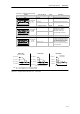
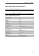
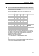
Table A-32 Setting RTD DIP Switches
Switch 6 Open Wire Detect/
OutofRange
Setting Description
Configuration
SW6 Upscale
(+3276.7 degrees)
0 Indicates positive on open wire or
out of range
↑1--On
↓0--Off
C
o
n
f
i
g
u
r
a
t
i
o
n
12345678
Downscale
(--3276.8 degrees)
1 Indicates negative on open wire or
out of range
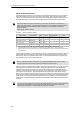
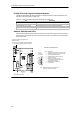
Switch 7 Temperature Scale Setting Description
↑
1
O
n
SW7
Configuration
Celsius (_C) 0 The RTD module can report
temperatures in Celsius or
Fahrenheit. The Celsius to
F
h
h
i
t
i
i
12345678
↑1--On
↓0--Off
Fahrenheit (_F) 1
Fahrenheit conversion is
performed inside the module.
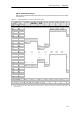
Switch 8 Wiring Scheme Setting Description
↑
1--On
Configuration
SW8
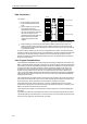
3-wire 0 You can wire the RTD module to
the sensor in three ways (shown in
the figure). The most accurate is 4
w
i
r
e
)
T
h
e
l
e
a
s
t
a
c
c
u
r
a
t
e
i
s
2
w
i
r
e
↑
1
--
O
n
↓0--Off
12345678
2-wire or 4-wire 1
wire
)
. The least accurate is 2 wire,
which is only recommended if
errors due to wiring can be ignored
in your application.
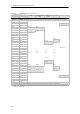
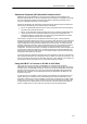
A+ Sense +
A-- Sense --
a+ Source +
a-- Source --
RTD
RTD 4 Wire
(most accurate)
A+ Sense +
A-- Sense --
a+ Source +
a-- Source --
RTD
If R
L1=
R
L2
, error is minimal.
RTD 3 Wire
R
L1
+R
L2
=Error
A+ Sense +
A-- Sense --
a+ Source +
a-- Source --
RTD
R
L1
R
L2
Set switch to
4-wire mode.
RTD 2 Wire
R
L1
R
L2
Note: R
L1
= Lead resistance from a+ terminal to the RTD
R
L2
= Lead resistance from a-- terminal to the RTD
R
L1
R
L2
Figure A-25 Wiring the RTD to the Sensor by 4, 3, and 2 Wire