
Specifications


Technical Specifications Appendix A
467
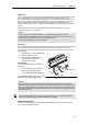
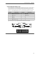
S7-200 USB/PPI Multi-Master Cable
To use the USB cable, you must have STEP 7--Micro/WIN 3.2 Service Pack 4 (or later) installed. It
is recommended that you use the USB cable only with an S7-200 CPU22x or later. The USB
cable does not support Freeport communications or downloading the TP Designer to the TP070.
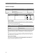
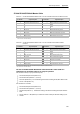
Table A-69 S7-200 USB/PPI Multi-Master Cable -- Pin-outs for the RS-485 to USB Series “A” Connector
RS-485 Connector Pin-out USB Connector Pin-out
Pin Number Signal Description Pin Number Signal Description
1 No connect 1 USB -- DataP
2 24 V Return (RS-485 logic ground) 2 USB -- DataM
3 Signal B (RxD/TxD+) 3 USB 5V
4 RTS (TTL level) 4 USB logic ground
5 No connect
6 No connect
7 24 V Suppl y
8 Signal A (RxD/TxD--)
9 Protocol select (low = 10 bit)
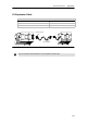
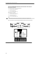
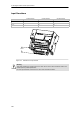
Figure A-45 shows the S7-200 USB/PPI Multi-Master Cable dimensions and LEDs.
130 mm
0.8 m
USB COMM RS-485 COMM
4.7 m
51 mm
Tx
LED
Rx
PPI
Green
Color
Green
Green
USB transmit indicator
Description
USB receive indi cator
RS-485 transmit indicator
Figure A-45 S7-200 USB/PPI Multi-Master Cable Dimensions and LEDs