Not Recommended for New Installations. Please contact Technical Support for more information. Stable Real Time Clock for PCs Model PCRTC Documentation Number PCRTC2095 This product Designed and Manufactured In Ottawa, Illinois USA of domestic and imported parts by B&B Electronics Mfg. Co. Inc. 707 Dayton Road -- P.O. Box 1040 -- Ottawa, IL 61350 PH (815) 433-5100 -- FAX (815) 433-5105 Internet: http://www.bb-elec.com orders@bb-elec.com support@bb.elec.
Table of Contents CHAPTER 1. GENERAL INFORMATION ....................................1 INTRODUCTION ........................................................................................1 PACKING LIST ..........................................................................................1 SPECIFICATIONS .......................................................................................1 CHAPTER 2. SETUP ..........................................................................2 HARDWARE SETUP......
Chapter 1. General Information Introduction The PCRTC is real time clock for PCs based on a highly stable oscillator circuit. Using the software driver provided, the PCRTC will update the DOS clock every minute, ensuring that all applications have access to accurate time information. With a simple function call, the PCRTC also reports battery status and the time of the last power loss or computer reset. Packing List Examine the shipping carton and contents for physical damage.
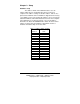
Chapter 2. Setup Hardware Setup The address switch on the PCRTC must be set to an address which doesn’t conflict with other devices in the host computer. The address settings are listed in Table 1, and are also printed on the PCRTC card. The PCRTC is shipped from the factory set for 200h. If you need to change this address, select one from the table which will not conflict with another device in the host computer. If the PCRTC does not operate properly, select a new address.
Hardware Installation 1. 2. 3. 4. Shut the host computer power off. Remove the computer cover. Remove the expansion slot cover of an unused slot. Handle the PCRTC only by its edges. Avoid touching any conductors on the PCRTC. Install the PCRTC into the slot. Be certain that the card is inserted completely into the slot. 5. Secure the card with the mounting screw from the slot cover. The PCRTC is shipped with the oscillator halted to extend battery life. To start the PCRTC, the card must be initialized.
Chapter 3. Operation Overview The most common application of the PCRTC is to simply maintain the correct time on the host computer. Loading the device driver in the CONFIG.SYS file will accomplish this function by setting the DOS clock to the PCRTC clock time once every minute. This allows the user and all applications access to the correct time without any special commands or function calls.
PCRTC v1.00, (c) Copyright 1995, B&B Electronics Mfg. Co. PCRTC address: 200h Battery Status: Good If this message appears, the driver has been installed and is running. The DOS clock will be updated every minute using the time from the PCRTC. The driver will report any errors found upon installation. Command Line Options All of the PCRTC features can be accessed and controlled from the command line as well. The program PCRTC.EXE has the following command line options.
The best method of updating the PCRTC time is to use the shareware program Timeset. Note that although this program is included on the PCRTC diskette, it is shareware and should be registered with its author. Timeset uses your modem to obtain the precise time from one of five atomic clocks in two continents, then sets your DOS time. The batch file RTCSET.BAT included in the Timeset directory should be used in conjunction with Timeset. Running the batch file will execute the following operations.
Start_RTC_API Purpose: Initializes API, must be the first PCRTC function called in the program. C: int Start_RTC_API(unsigned int address); Pascal: FUNCTION Start_RTC_API(address: WORD): WORD; BASIC: FUNCTION StartRTCAPI% (BYVAL address AS INTEGER) Remarks: Start_RTC_API takes the address at which the PCRTC is installed at. The device driver must be installed. Returns: 0 = device driver is not installed. non zero = address of PCRTC. Example: See below.
Get_RTC_Time Purpose : Returns the RTC time within a structure.
Last_Power_Down_RTC Purpose: Returns date and time of last power down within a structure.
QuickBASIC Example: '$INCLUDE: 'RTC_API.BI' ‘Must be first executed statement in your program DIM timeS AS TimeSaveT DIM time AS GetTimeT ‘Define Variable Structure address% = StartRTCAPI(0) ‘Initialize API IF (address% <> 0) THEN ‘Check that it initialized OK IF (GetRTCTime(VARSEG(time), VARPTR(time)) <> 0) THEN PRINT “RTC time: “; time.hours; “:”; time.min; “:”; time.seconds; “.”; PRINT time.
C Programming Example #include #include "rtc_api.h" void main() { TimeSave_T *ts = (TimeSave_T *) malloc(sizeof(TimeSave_T)); GetTime_T *time = (GetTime_T *) malloc(sizeof(GetTime_T)); unsigned int battery; unsigned int address; cprintf("Demo (PCRTC-c) v1.00, (c) Copyright 1994, B&B Electronics Mfg. Co.\r\n\r\n"); address = Start_RTC_API(0); if (address) { if (Get_RTC_Time(time)) cprintf(“RTC time: %u:%u:%u.
Chapter 4. Calculating Error PPM Terminology The unit ppm (parts per million) provides a number similar to error expressed with percentages, but reduces the number of decimal places required. For example, 0.001% converts to 0.00001 which is equivalent to 10 ppm. Using the ppm notation makes it easier to deal with very small deviations. The ppm terminology is also useful for calculating PCRTC error in terms of seconds per month. Since an average month has approximately 2.
Aging All crystal oscillators have an aging characteristic. The crystal used in the PCRTC uses the coldweld manufacturing technique, which exhibits the lowest aging characteristic of 1 ppm/year. In practice, this aging rate improves significantly with time, but for practical purposes the value of 1 ppm is adequate. To estimate the error in your application, sum the error from the three sources above.
Appendix A.
Hardware I/O Map of AT Class Machines Hex Address Address Function in AT Class Machines 000-01F DMA controller #1 (8237A-5) 020-03F interrupt controller #1 (8259A) 040-05F timer (8254) 060-06F keyboard (8042) 070-07F NMI - non maskable interrupt & CMOS RAM 080-09F DMA page register (74LS612) 0A0-0BF interrupt controller #2 (8259A) 0C0-0DF DMA controller #2 (8237A) 0F0-0FF 80287 math coprocessor 1F0-1F8 hard disk 200-20F game port joystick controller 258-25F Intel Above Board 278-27F parallel printer port 2