
Specifications


16 RS-422/485 Application Note
Copyright B&B Electronics -- Revised October 1997
B&B Electronics -- PO Box 1040 -- Ottawa, IL 61350
PH (815) 433-5100 -- FAX (815) 434-7094
Termination
Termination is used to match impedance of a node to the impedance of the
transmission line being used. When impedance are mismatched, the transmitted
signal is not completely absorbed by the load and a portion is reflected back into
the transmission line. If the source, transmission line and load impedance are
equal these reflections are eliminated. There are disadvantages of termination as
well. Termination increases load on the drivers, increases installation
complexity, changes biasing requirements and makes system modification more
difficult.
The decision whether or not to use termination should be based on the cable
length and data rate used by the system. A good rule of thumb is if the
propagation delay of the data line is much less than one bit width, termination is
not needed. This rule makes the assumption that reflections will damp out in
several trips up and down the data line. Since the receiving UART will sample
the data in the middle of the bit, it is important that the signal level be solid at
that point. For example, in a system with 2000 feet of data line the propagation
delay can be calculated by multiplying the cable length by the propagation
velocity of the cable. This value, typically 66 to 75% of the speed of light (c), is
specified by the cable manufacture.
For our example, a round trip covers 4000 feet of cable. Using a
propagation velocity of 0.66 × c, one round trip is completed in approximately
6.2 µs. If we assume the reflections will damp out in three “round trips” up and
down the cable length, the signal will stabilize 18.6 µs after the leading edge of a
bit. At 9600 baud one bit is 104 µs wide. Since the reflections are damped out
much before the center of the bit, termination is not required.
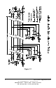
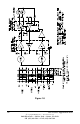
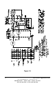
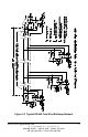
There are several methods of terminating data lines. The method
recommended by B&B is parallel termination. A resistor is added in parallel
with the receiver’s “A” and “B” lines in order to match the data line
characteristic impedance specified by the cable manufacture (120 Ω is a
common value). This value describes the intrinsic impedance of the
transmission line and is not a function of the line length. A terminating resistor
of less than 90 Ω should not be used. Termination resistors should be placed
only at the extreme ends of the data line, and no more than two terminations
should be placed in any system that does not use repeaters. This type of
termination clearly adds heavy DC loading to a system and may overload port
powered RS-232 to RS-485 converters. Another type of termination, AC
coupled termination, adds a small capacitor in series with the termination resistor
to eliminate the DC loading effect. Although this method eliminates DC loading,
capacitor selection is highly dependent on the system properties. System