
Specifications


RS-422/485 Application Note 23
Copyright B&B Electronics -- Revised October 1997
B&B Electronics -- PO Box 1040 -- Ottawa, IL 61350
PH (815) 433-5100 -- FAX (815) 434-7094
Chapter 4: Transient Protection of RS-422 and RS-485
Systems
The first step towards protecting an RS-422 or RS-485 system from
transients is understanding the nature of the energy we are guarding against.
Transient energy may come from several sources, most typically environmental
conditions or induced by switching heavy inductive loads.
What does a surge look like?
Surge Specifications
While transients may not always conform to industry specifications, both the
Institute of Electrical and Electronics Engineers (IEEE) and the International
Electrotechnical Commission (IEC) have developed transient models for use in
evaluating electrical and electronic equipment for immunity to surges. These
models can offer some insight into the types of energy that must be controlled to
prevent system damage.
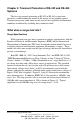
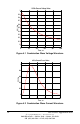
Both IEC 1000-4-5: 1995 “Surge Immunity Test” and IEEE C62.41-1991
“IEEE Recommended Practice on Surge Voltages in Low-Voltage AC Power
Circuits” define a “1.2/50µs - 8/20µs combination wave” surge which has a 1.2
µs voltage rise time with a 50 µs decay across an open circuit. The specified
current waveform has an 8 µs rise time with a 20 µs decay into a short circuit.
Open circuit voltages levels from 1 to 6 kV are commonly used in both the
positive and negative polarities, although under some circumstances voltages as
high as 20 kV may be applied. Figures 4.1 and 4.2 illustrate the combination
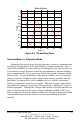
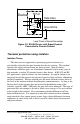
wave characteristics. In addition, IEEE C62.41 also specifies a 100 kHz “ring
wave” test. The ring wave has a 0.5 µs rise time and a decaying oscillation at
100 kHz with source impedance of 12Ω as shown in Figure 4.3. Typical
amplitudes for the 100 kHz ring wave also range from 1 – 6 kV.